Fluid dispensing apparatus

Active Publication Date: 2005-02-17
SAKURA FINETEK U S A
View PDF98 Cites 64 Cited by
  • Summary
  • Abstract
  • Description
  • Claims
  • Application Information

AI Technical Summary

Benefits of technology

[0007] The present invention alleviates to a great extent the above-noted and other disadvantages of known fluid dispensing apparatus by providing a fluid dispensing cartridge that

Problems solved by technology

One disadvantage associated with conventional reagent dispensing systems (such as disclosed in U.S. Pat. No. 5,232,664) concerns the use of a contact actuator assembly to control the dispensing of reagent.
A further disadvantage associated with conventional reagent dispensing systems involves uncontrolled or er

Method used


Image

  • Fluid dispensing apparatus
  • Fluid dispensing apparatus
  • Fluid dispensing apparatus

Examples


Embodiment Construction

[0024] In the following paragraphs, the present invention will be described in detail by way of example with reference to the attached drawings. Throughout this description, the preferred embodiment and examples shown should be considered as exemplars, rather than as limitations on the present invention. As used herein, the “present invention” refers to any one of the embodiments of the invention described herein, and any equivalents. Furthermore, reference to various feature(s) of the “present invention” throughout this document does not mean that all claimed embodiments or methods must include the referenced feature(s).

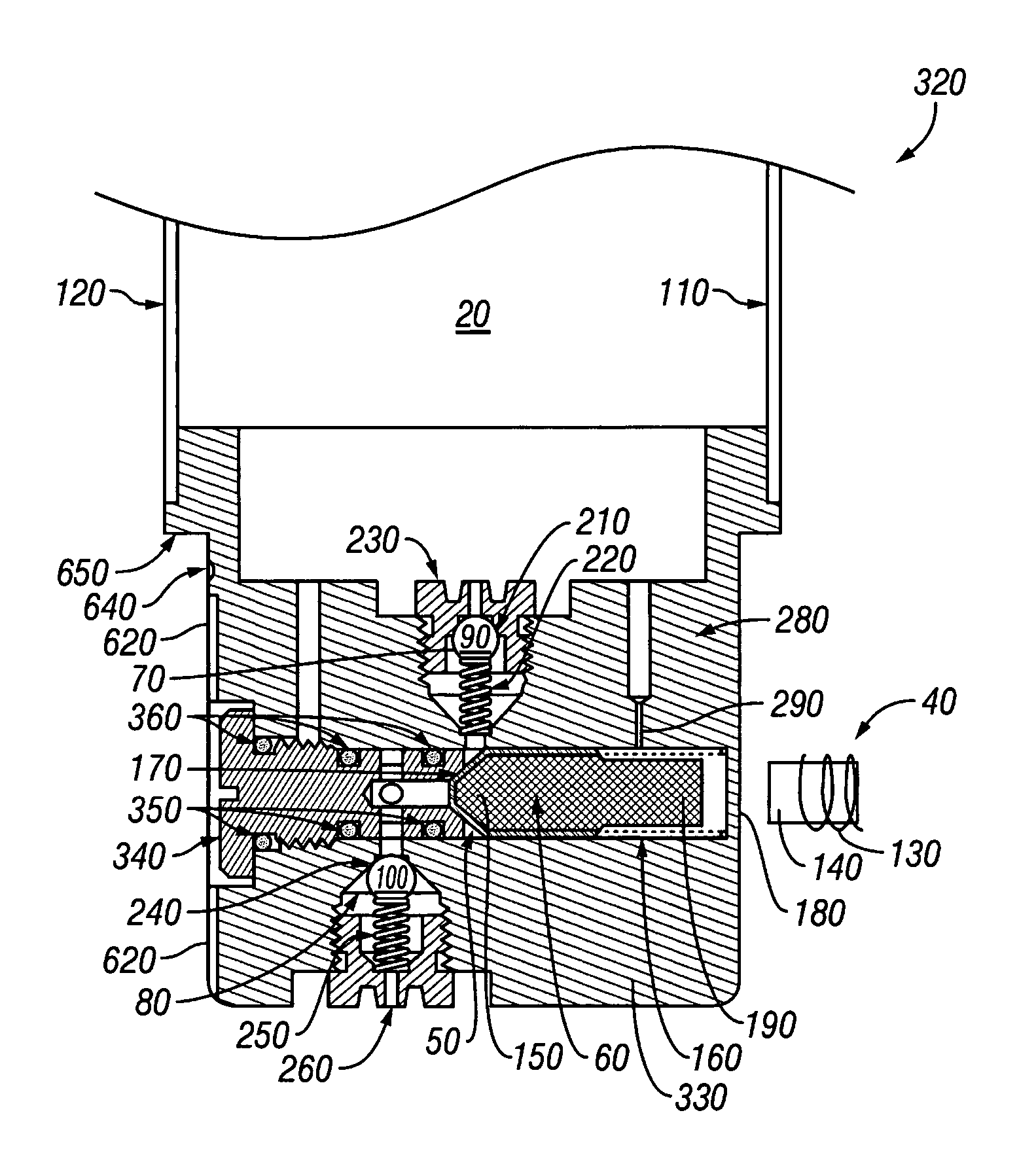
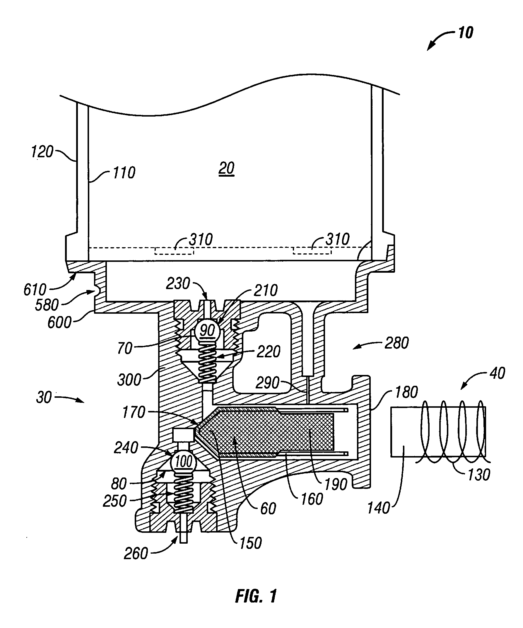
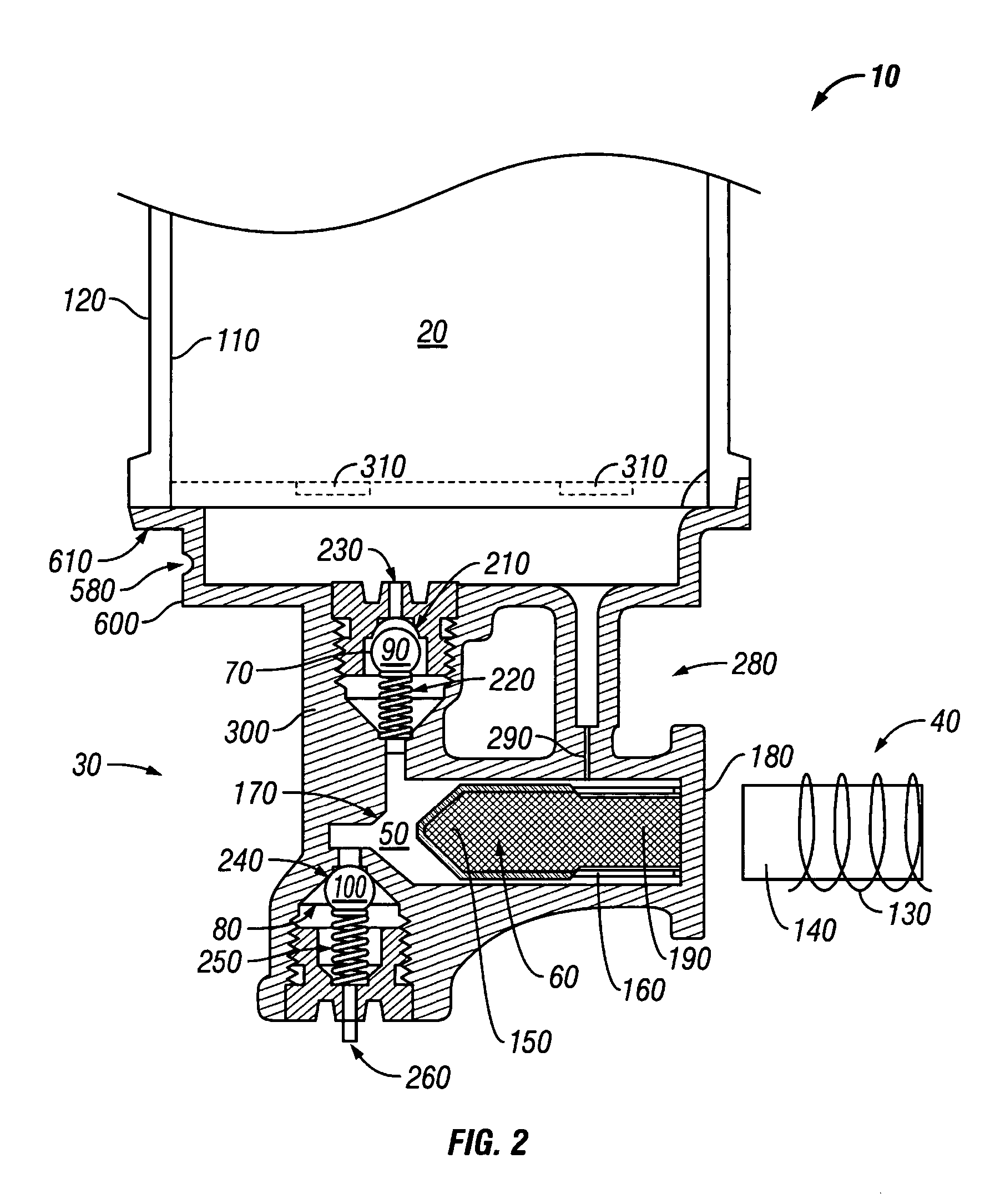
[0025]FIGS. 1-3 show a preferred embodiment of a fluid dispensing cartridge10 in accordance with the present invention. The fluid dispensing cartridge 10 includes a fluid reservoir 20, a fluid dispensing assembly 30 in communication with the fluid reservoir 20 and an actuator assembly 40. The fluid dispensing assembly 30 includes a fluid metering chamber 50, a pist...


PUM


Abstract

A fluid dispensing apparatus includes a mounting assembly having a plurality of mounting apertures and a plurality of fluid dispensing cartridges positioned within the mounting apertures. The mounting apertures and cartridges include matching cross-sectional profiles that lack symmetry. Each fluid dispensing cartridge includes a fluid reservoir, at least one valve, a metering chamber and a piston. The apparatus also includes a magnetic switch assembly controlling the movement of the piston and a means for damping the movement of the piston.

Description

FIELD OF THE INVENTION [0001] The present invention relates to medical laboratory fluid dispensing devices and related systems. BACKGROUND OF THE INVENTION [0002] While conducting biological tests, it often is necessary to dispense liquids such as reagents onto test slides containing tissue specimens. When analyzing tumor tissue for example, a thinly sliced section of the tissue might be placed on a slide and processed through a variety of steps, including dispensing predetermined amounts of liquid reagents onto the tissue. Automated reagent fluid dispensing devices have been developed to precisely apply a sequence of preselected reagents to test slides. [0003] One example of a known reagent dispensing system is illustrated in U.S. Pat. No. 5,232,664. In this system, a reagent dispensing tray can receive plural reagent containers and may include a means for positioning selected reagent containers over slides to receive reagent. An air cylinder or equivalent actuator makes contact wi...

Claims


Application Information

Patent Timeline
IPC IPC(8): B01L3/02B67D7/16B67D7/30B67D7/64G01F11/02G01N35/10
CPCB01L3/0206B01L3/0265B01L2200/0605B01L2400/0478B01L2400/0633B01L2400/0666G01F11/021G01N35/1002Y10T436/112499Y10T436/2575
Inventor HERSCH, MICHAELPALERMO, HENRY
Owner SAKURA FINETEK U S A
Why Eureka
Try Eureka