Automatic methods for focus and astigmatism corrections in charged-particle beam instrument

a scanning charged particle and beam instrument technology, applied in the direction of instruments, heat measurement, photomechanical equipment, etc., can solve the problems of difficult to distinguish the two peaks, difficult to determine the focus, and difficult to make such a judgmen

a scanning charged particle and beam instrument technology, applied in the direction of instruments, heat measurement, photomechanical equipment, etc., can solve the problems of difficult to distinguish the two peaks, difficult to determine the focus, and difficult to make such a judgmen

US20050035290A1Inactive Publication Date: 2005-02-17JEOL LTD

Image

  • Automatic methods for focus and astigmatism corrections in charged-particle beam instrument
  • Automatic methods for focus and astigmatism corrections in charged-particle beam instrument
  • Automatic methods for focus and astigmatism corrections in charged-particle beam instrument

Examples


Embodiment Construction

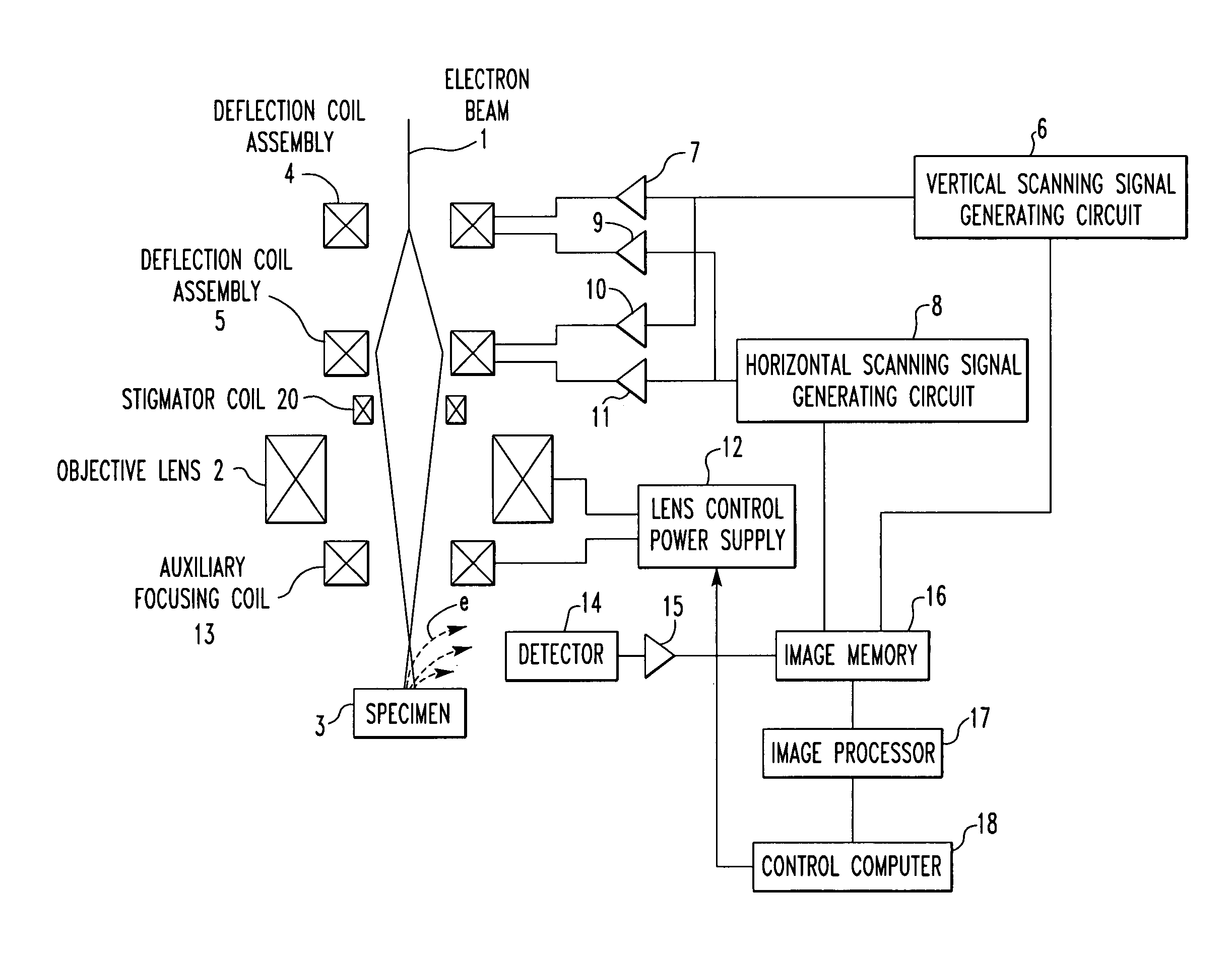
[0055] The preferred embodiments of the present invention are hereinafter described in detail with reference to the accompanying drawings. FIG. 4 shows a scanning electron microscope for implementing the present invention.

[0056] The microscope has an electron gun (not shown) emitting an electron beam 1. The beam 1 is sharply focused onto a specimen 3 to be observed, using a condenser lens (not shown) and an objective lens 2. The strength of the electron beam 1, or beam current, is adjusted by the condenser lens (not shown) and an objective lens aperture.

[0057] After the strength of the electron beam 1 has been adjusted, the beam is scanned in two dimensions over the specimen 3 by two stages of deflection coil assemblies 4 and 5. Each of the upper-stage deflection coil assembly 4 and lower-stage deflection coil assembly 5 has horizontal and vertical deflection coils. A vertical scanning signal is supplied to the vertical deflection coil of the upper-stage deflection coil assembly 4...


PUM

PropertyMeasurementUnit
angleaaaaaaaaaa
strengthaaaaaaaaaa
areaaaaaaaaaaa

Abstract

Automatic methods for focus and astigmatism corrections in a charged-particle beam instrument find an amount of excitation of the objective lens that provides the position of a circle of least confusion and can perform accurate automatic corrections of focus and astigmatism. The edge components of the original image along the X- and Y-directions are extracted separately, using respective filters. Noise reduction and normalization of numerical values are performed for each of the resulting two sets of data. Two-dimensional matrices of numerical values indicating the edge components in the X- and Y-directions, respectively, are found independently. The sums of the elements of the matrices are taken as focus evaluation values of the original image in the X- and Y-directions, respectively.

Description

BACKGROUND OF THE INVENTION [0001] 1. Field of the Invention [0002] The present invention relates to automatic methods for focus and astigmatism corrections in a scanning charged-particle beam instrument, such as a scanning electron microscope, having functions of automatic focus correction and automatic astigmatic correction. [0003] 2. Description of Related Art [0004] A scanning electron microscope, which is a typical example of scanning charged-particle beam instrument, is now described. In a scanning electron microscope, an electron beam produced from an electron gun is accelerated toward a specimen. The accelerated beam is sharply focused onto the specimen by a condenser lens and an objective lens. The beam is also scanned across a desired area on the specimen by deflection coils. The strength of the beam, i.e., the amount of beam current, is adjusted by the condenser lens and an objective lens aperture (baffle). In this microscope, secondary electrons produced by scanning the ...

Claims


Application Information

Patent Timeline
17 Feb 2005
Publication
US20050035290A1
IPC
H01J37/153; H01J37/21; G03F7/207; H01J37/22; H01J37/256; H01J37/28; H01L21/027
CPC
H01J37/153; H01J37/21; H01J2237/216; H01J37/28; H01J37/222
Inventors
SAITOH, MANABU