Cast carrier element for a vehicle body

a carrier element and vehicle body technology, applied in the direction of roofs, transportation and packaging, vehicle arrangements, etc., can solve the problems of insufficient strength of the support element in the event of overturning and insufficient crash safety, so as to reduce the weight of the support element, increase the strength-increasing effect, and ensure the effect of safety

Inactive Publication Date: 2005-02-17
DAIMLER AG
View PDF20 Cites 26 Cited by
  • Summary
  • Abstract
  • Description
  • Claims
  • Application Information

AI Technical Summary

Benefits of technology

[0005] An object of this invention is to provide a support element which has a lower weight compared with the prior art at the same or improved strength.
[0007] A support element according to the invention is produced from cast iron. An advantage compared with the conventional steel sheets used in vehicle body construction is that, in structures of cast iron, the material thickness can be adapted to the forces which occur. It is thus possible by means of loading simulations to determine the regions with the highest mechanical loads and to reinforce the material in these regions. On the other hand, in regions subjected to low load, material can be saved. By optimizing these methods, a weight saving of over 50% compared with a steel sheet construction can be achieved in a support element having the same function.
[0008] Compared with a construction of cast aluminum, the invention has an advantage in higher strength and greater elongation of the iron materials compared with the cast aluminum materials. By the described displacement of material and saving of material, support elements can be produced which, with the same function, have a mass similar to that of cast aluminum components, but can instead be mechanically loaded to a substantially greater extent.
[0009] The support element, in a cavity, is filled with a core of hollow balls or an iron-based metal foam (iron foam). The hollow balls or the iron foam, as core material, lead to an increase in mechanical strength, the weight of the support element increasing only marginally. In addition, the hollow balls help to improve the damping of body vibrations.
[0013] At the surface or the struts or ribs, the support element preferably has a wall thickness which is less than 3 mm. Due to such wall thicknesses, the weight of the support element is reduced while ensuring sufficient strength.
[0014] The hollow balls are connected to one another, as a result of which their strength-increasing effect is increased even further.

Problems solved by technology

In the case of the A-columns of motor vehicles, in particular of convertibles, the strength of the support element in the event of overturning is often not high enough in order to ensure a sufficient survival space for the occupants.
Although this type of construction offers a high potential for saving weight, crash safety is not ensured by this simple zigzag structure, since it has no suitable reinforcement in particular for a side collision.

Method used


Image

  • Cast carrier element for a vehicle body
  • Cast carrier element for a vehicle body
  • Cast carrier element for a vehicle body

Examples


Embodiment Construction

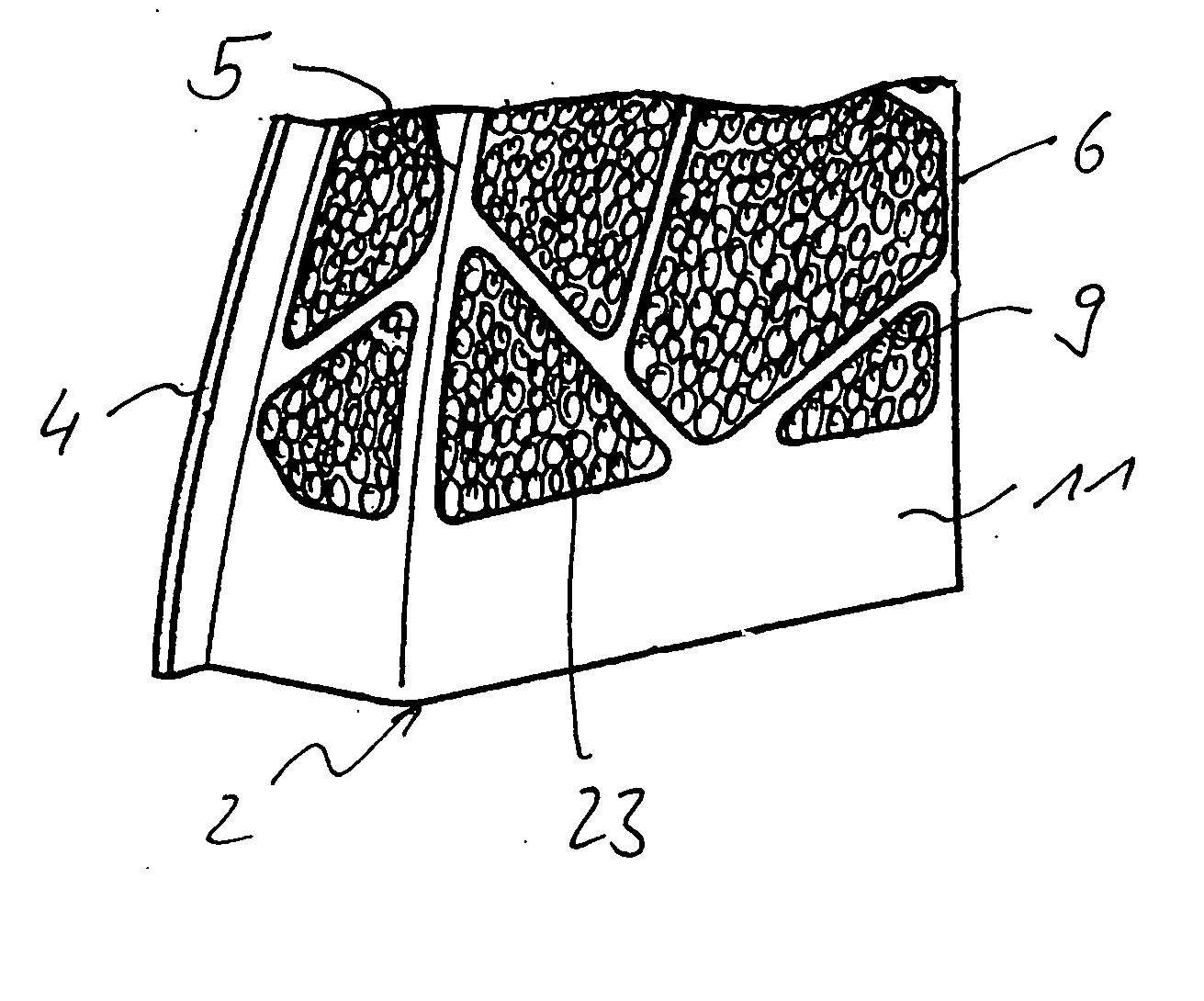
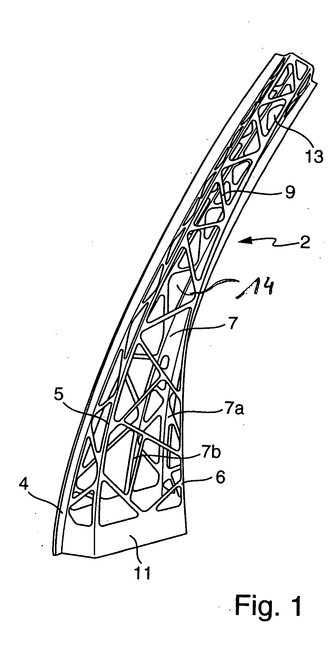
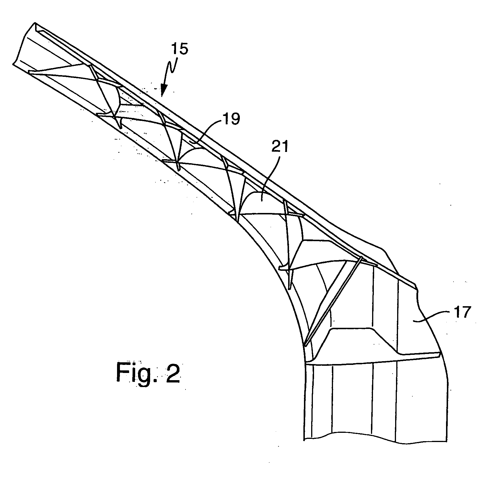
[0024] The support element 2 shown in FIG. 1 is designed in the form of an A-column of a motor vehicle. In order to more clearly show the support element, the hollow balls embedded according to the invention are not depicted in the support elements in FIGS. 1 and 2.

[0025] The support element in FIG. 1 has four longitudinal struts 4-7, the longitudinal strut 7 branching in the bottom region (7a and 7b). The support element 2 consists of a shell element, which in this case is identical to the support element 2. The longitudinal struts 4-7 and 7a, b are connected by transverse struts 9. The longitudinal struts 4-7, 7a, b and the transverse struts 9 together produce a lattice structure which forms the surface of the support element but is open in wide regions.

[0026] In the base region, the support element 2 has an encircling transverse strut 11 which is designed to be markedly wider than the other transverse struts 9. The transverse strut 11 is to be regarded as exemplary; likewise, i...


PUM

PropertyMeasurementUnit
thicknessaaaaaaaaaa
wall thicknessaaaaaaaaaa
diameteraaaaaaaaaa

Abstract

The invention relates to a support element for a vehicle body, in particular for supporting columns, the support element being produced from cast iron. The support element is designed, for example, as a lattice structure and is filled with metallic hollow balls for additional reinforcement.

Description

BACKGROUND AND SUMMARY OF THE INVENTION [0001] The present invention relates to a support element for a vehicle body and to a method of producing a support element. [0002] Support elements of vehicle bodies are as a rule composed of metal sheets of constant wall thickness. These sheets are often formed into half shells and a plurality of half shells are welded to form a support element or structure element. In the case of the A-columns of motor vehicles, in particular of convertibles, the strength of the support element in the event of overturning is often not high enough in order to ensure a sufficient survival space for the occupants. [0003] To ensure crash safety, the roof columns, in particular the A-columns of convertibles, are reinforced with a steel tube which runs in the center of the column. Such an A-column establishing the generic type is described in German publication DE 40 16 730 C2. [0004] In the course of extensive attempts to achieve lightweight construction in auto...

Claims


Application Information

Patent Timeline
Patent Type & Authority Applications(United States)
IPC IPC(8): B22D19/02B62D25/04
CPCB62D25/04B22D19/02
Inventor BEHR, THOMASEIPPER, KONRADFUSSNEGGER, WOLFGANGGERICK, ARNDTKLEINEKATHOEFER, WOLFGANGMINNICH, DANIELSCHEFFZUEK, MATTIAS
Owner DAIMLER AG
Why Eureka
Try Eureka