
Variable reluctance resolver including rotor with multiple detection portions

Inactive Publication Date: 2005-02-17
MINEBEA CO LTD
View PDF7 Cites 3 Cited by
  • Summary
  • Abstract
  • Description
  • Claims
  • Application Information

AI Technical Summary

Benefits of technology

[0014] With the VR resolver of the present invention, two or more detection signals are generated simultaneously rather than one, and two or more detection signals are detected simultaneously by a plurality of zero point detection windings to identify the zero point. Therefore, even if a detection signal is lost due to, for example, a detection error, the zero point can be detected with high precision and reliability. In addition, the detection signal can be detected as an incremental signal, and detection of the absolute angle position can also be carried out.

Problems solved by technology

However, as the counter measures 1 to n of the electrical zero point signals and converts these signals to an absolute angle, the absolute angle cannot be detected when the count value of the counter is lost due to an error such as a detection error.
However, such a resolver is impractical from an implementation standpoint because it requires approximately twice the number of parts and configuration space compared to a resolver that does not include such a redundant connection.

Method used


Image

  • Variable reluctance resolver including rotor with multiple detection portions
  • Variable reluctance resolver including rotor with multiple detection portions
  • Variable reluctance resolver including rotor with multiple detection portions

Examples


Embodiment Construction

[0022] The VR resolver of the present invention will now be described in detail in accordance with the drawings. Illustration and description of components are omitted where not necessary for one skilled in the art to understand the present invention.

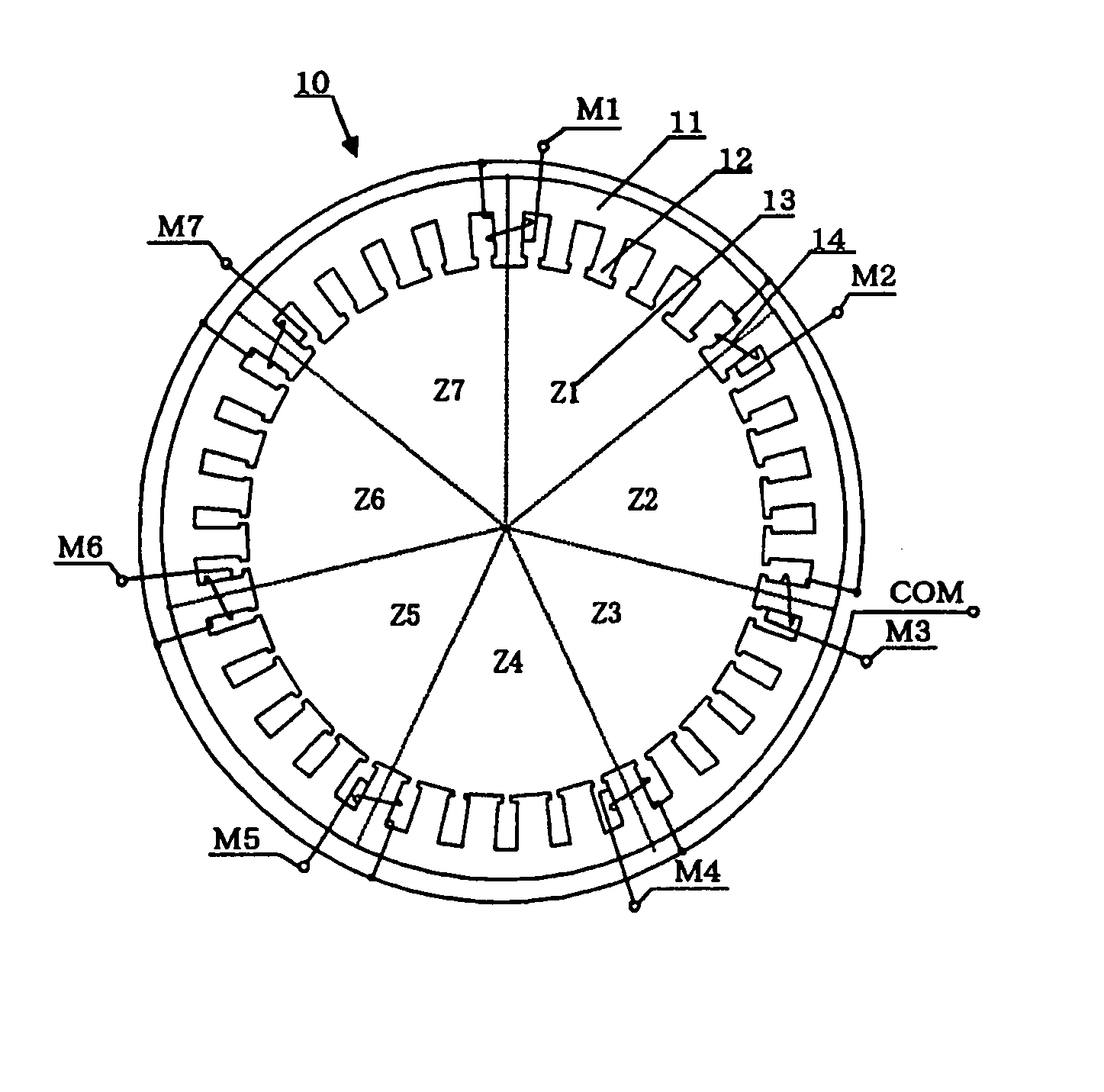
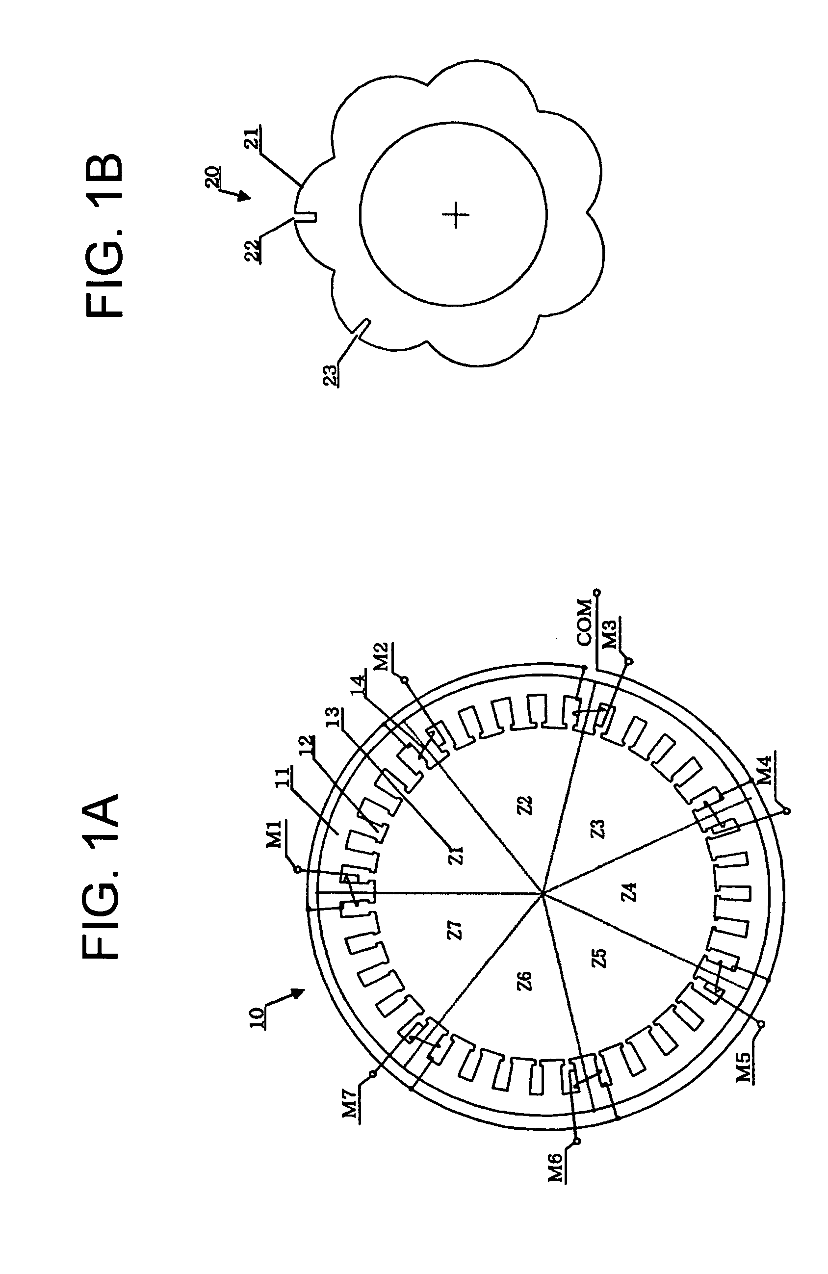
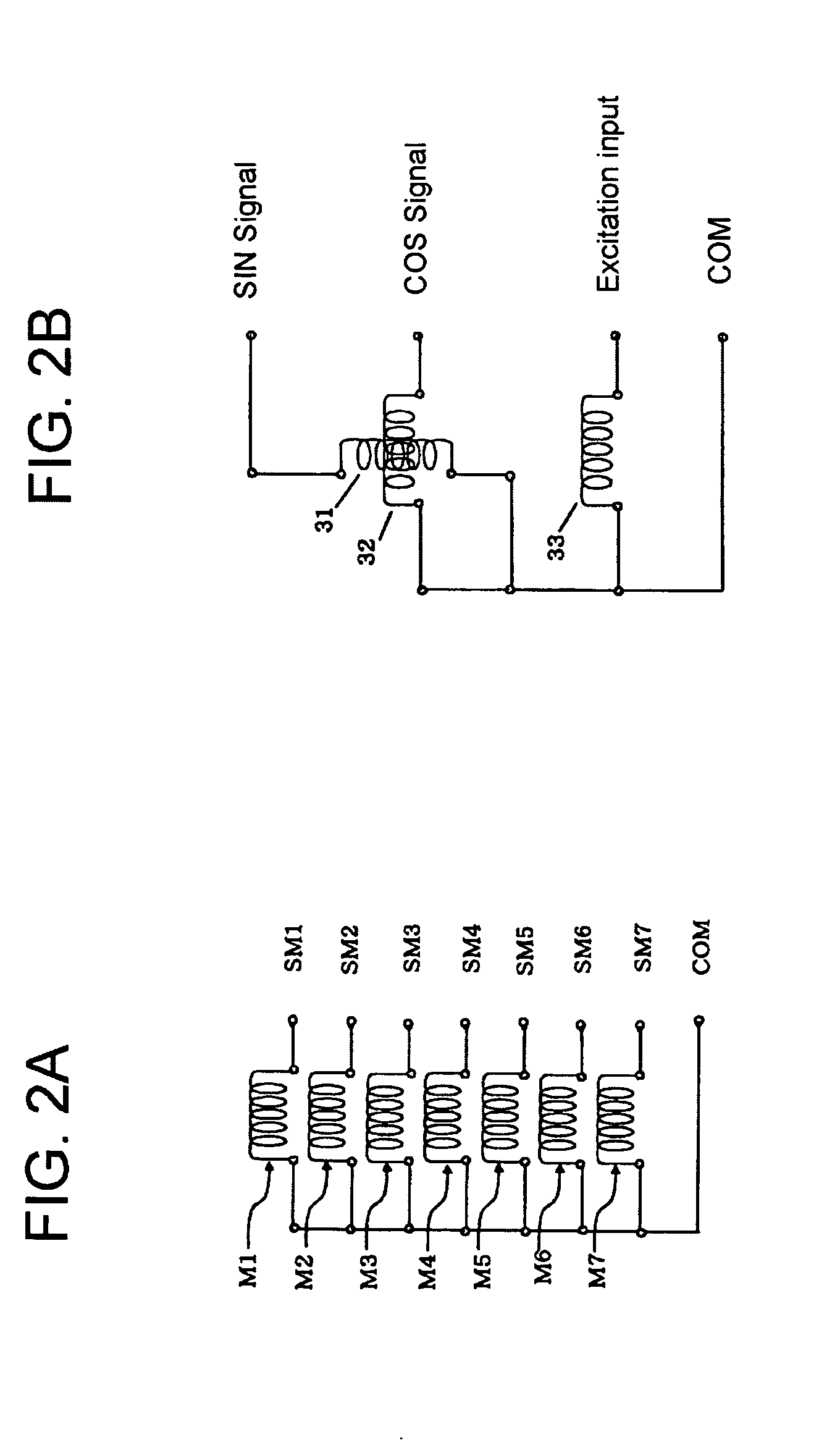
[0023] Referring to FIGS. 1A-1B and 2A-2B, a stator 10 of a VR resolver of the present invention includes a plurality of stator magnetic poles 12 on a magnetic stator yoke 11. An excitation winding 33, output windings that include a sine winding 31 and a cosine winding 32, and zero point detection windings 14 are wound around the stator magnetic poles 12. The marker windings are windings provided to detect the rotation angle of a resolver rotor 20. In addition, the marker windings serve as zero point detection windings.

[0024] Regarding the output windings, the sine winding 31 that outputs sine signals and cosine winding 32 that outputs cosine signals are provided so that the phases thereof are shifted by 90°. The excitation winding 33...


PUM


Abstract

A variable reluctance resolver has a rotor with magnetic poles with 2× or greater axis combination angles, and is structured so that reliable and accurate zero point detection can be carried out. Concave and convex portions are provided on at least two, but fewer than all, of the magnetic poles of the rotor, and the zero point detection winding is provided on a plurality of electrical poles of the stator. Two or more zero point detection signals are generated simultaneously by a plurality of zero point detection windings. Therefore, even if a portion of the zero point detection signals is lost, the zero point can still be identified based on the correlation between the two or more zero point detection signals.

Description

CROSS REFERENCE TO RELATED APPLICATION [0001] This application is based on and incorporates by reference Japanese Patent Application No. 2003-291223, which was filed on Aug. 11, 2003. BACKGROUND OF THE INVENTION [0002] The present invention relates to a Variable Reluctance resolver (VR resolver) having a zero point detector, and in particular a VR resolver that is capable of accurately and reliably detecting a zero point of a resolver rotor by detecting multiple detection portions provided on the rotor. [0003] A conventional VR resolver is effective as an incremental rotation sensor because a resolver output signal, which includes the sine signal and cosine signal output from a resolver output winding, is output n times per one revolution of the resolver rotor. FIG. 5 shows the correlation between an electrical zero point signal, the resolver output signal and the resolver angle with the axis combination angle nX, where nX=360°. [0004] As graphically shown in FIG. 5, in a convention...

Claims


Application Information

Patent Timeline
IPC IPC(8): G01D5/245G01D5/20G01D5/244G01P3/487H02K24/00
CPCG01D5/2046H02K24/00G01P3/487
Inventor MIYA, TAIICHIKASAHARA, TAROKOYAMA, TOSHISADA
Owner MINEBEA CO LTD
Learn More