
A rotating mechanism driven by shape memory alloy

A technology of rotating mechanism and memory alloy, which is applied in the direction of mechanical power generating mechanism, machine/engine, mechanical equipment, etc. It can solve the problems of complex equipment, small output, complex mechanism, etc., and achieve precise and reliable mechanism, low driving voltage, The effect of high mechanism precision

Active Publication Date: 2019-11-19
XIDIAN UNIV
View PDF5 Cites 0 Cited by
  • Summary
  • Abstract
  • Description
  • Claims
  • Application Information

AI Technical Summary

Problems solved by technology

After analysis, it is found that there are the following limitations: First, the motor-driven rotating mechanism needs to design a specific connection structure, angle control structure and reversing structure, etc., which often makes the rotating mechanism larger in size and complicated in mechanism
Second, the rotating mechanism of electromagnetic drive and gas-hydraulic drive has the disadvantages of complex equipment, high price, and low conversion efficiency of electric energy to mechanical energy.
Thirdly, the traditional reversible rotating mechanism, although the toothed plate can be forward and reversed, but the push rod and the toothed plate need to contact each other due to the connection of the reversing mechanism, and often do not have the idling function of the toothed plate. It will lead to certain limitations in the scope of application of the existing reversible rotating mechanism
[0005] At the same time, the existing SMA driver mainly uses SMA element wire or coil spring as the driving element. The wire has a large output and high efficiency, but the stroke is small; the stroke of the coil spring is large, but the efficiency is low and the output is small.

Method used


Image

  • A rotating mechanism driven by shape memory alloy
  • A rotating mechanism driven by shape memory alloy
  • A rotating mechanism driven by shape memory alloy

Examples


Embodiment Construction

[0046] The present invention will be described in detail below in conjunction with the accompanying drawings and specific embodiments, where the schematic embodiments and descriptions of the present invention are used to explain the present invention, but not to limit the present invention.

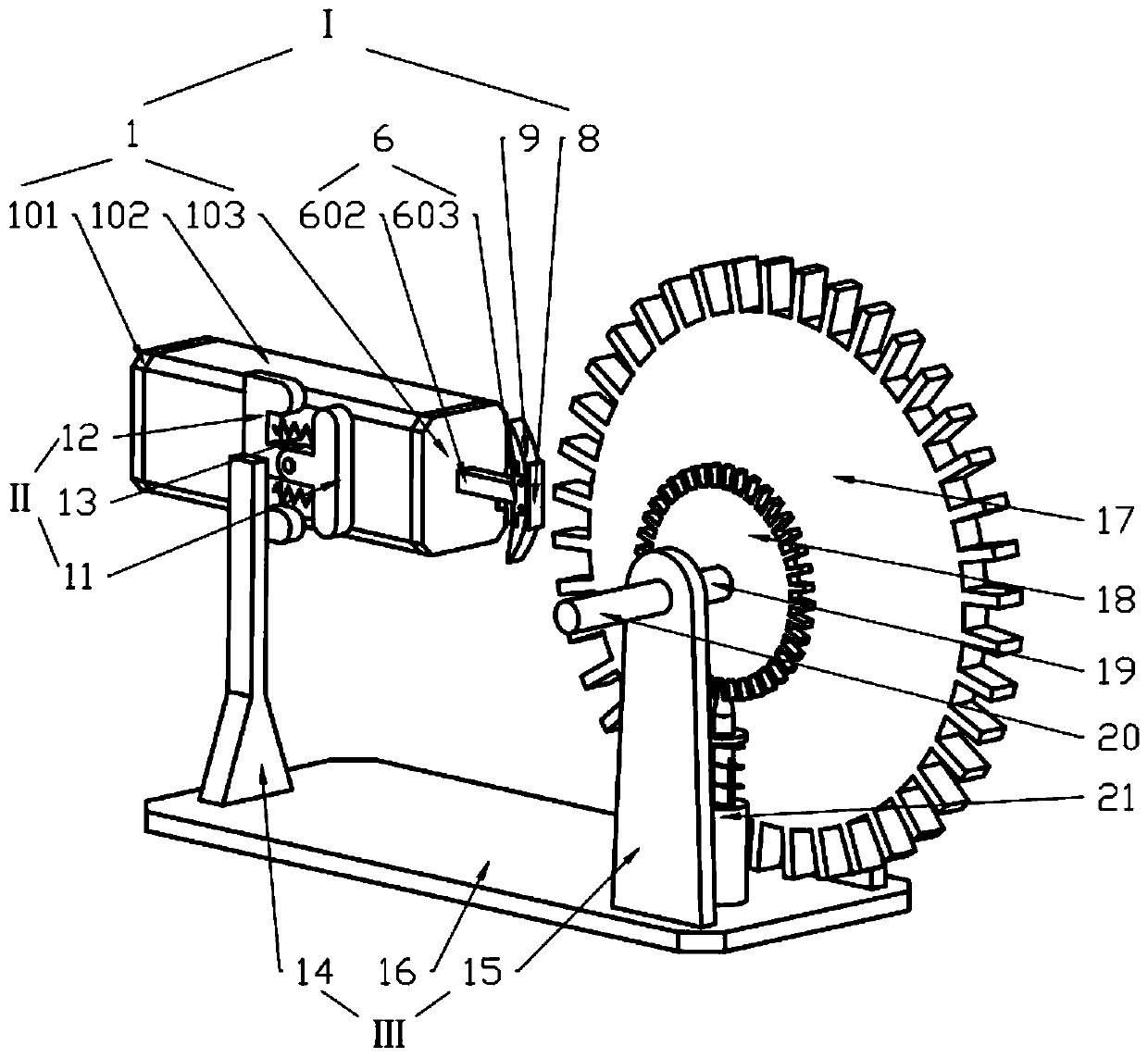
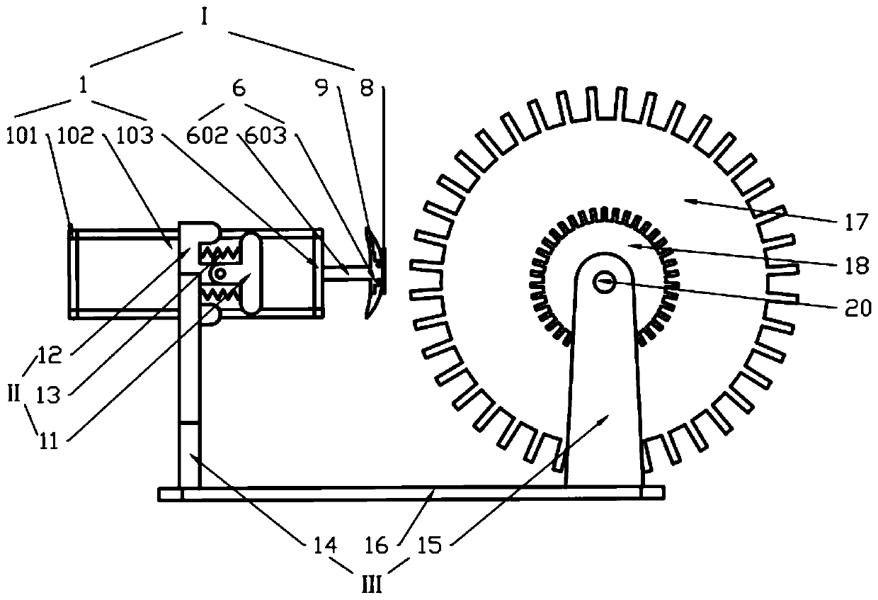
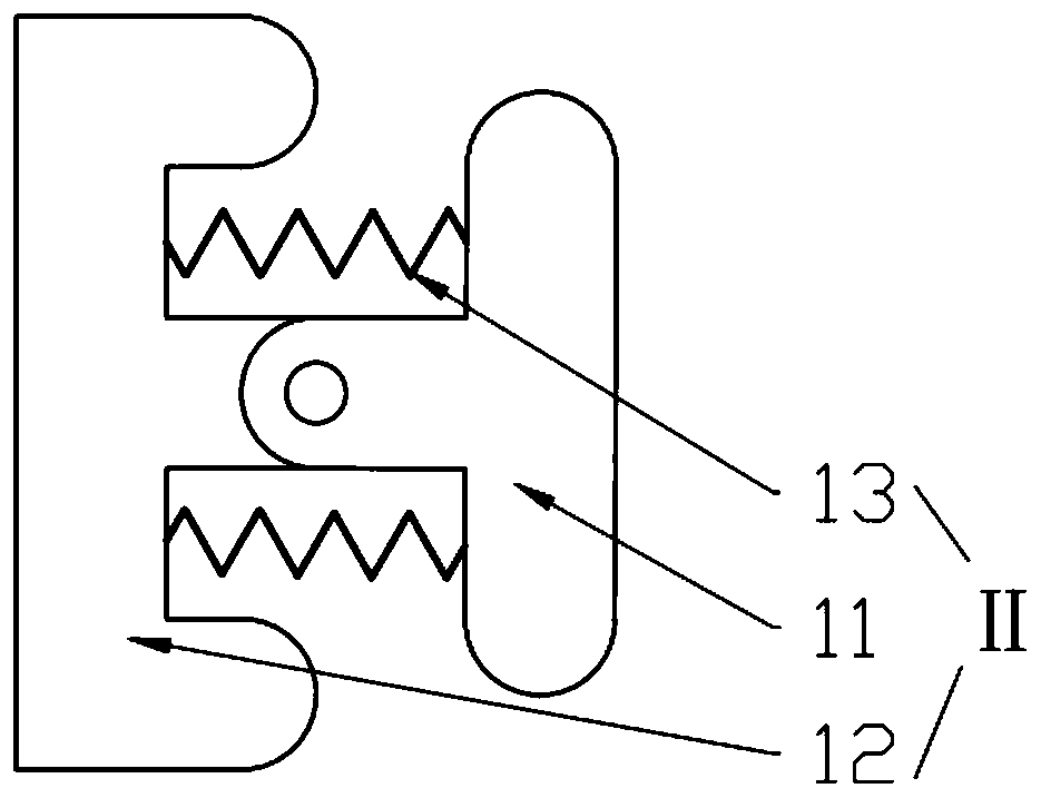
[0047] Referring to Fig. 1 (a), shown in Fig. 1 (b), a kind of shape memory alloy driven rotating mechanism of the present invention comprises a base III as a supporting structure, a rotating mechanism fixed on the base III, and An SMA oscillator II fixed on the base III for controlling the rotation direction of the rotating mechanism, and an SMA driver I for driving the rotation of the toothed plate 17 of the rotating mechanism. The base includes a first bracket 14 fixedly connected to the lower swing frame of the SMA oscillator, and a second bracket 15 supporting the chainring 17 .

[0048]Wherein, the rotating mechanism includes a central shaft 19 hinged on the second support frame 15 ...


PUM


Abstract

The invention discloses a shape memory alloy driven rotating mechanism which comprises a rotating mechanism fixed to a base III, an SMA oscillator II fixed to the base III for controlling the rotatingdirection of the rotating mechanism and an SMA driver I connected to the SMA oscillator II for pushing a fluted disc of the rotating mechanism to rotate, wherein the SMA fluted disc II comprises twooscillating racks; electrified SMA springs are separately connected between the oscillating racks; the SMA driver comprises an SMA elastic telescopic mechanism; the electrified SMA spring shrinks to drive the SMA oscillator II to oscillate while the SMA elastic telescopic mechanism of the electrified SMA driver I shrinks to push the fluted disc to rotate intermittently through a push rod claw on apush rod. The structure taking an SMA wire as a power source is very high in the ratio of output power and weight, small in driving voltage, small in size, simple in structure, noise-free, magnetism-free and convenient to control and is of very high popularization.

Description

technical field [0001] The invention relates to the field of mechanical transmission, and relates to a rotating mechanism, in particular to an intermittent rotating mechanism driven by a shape memory alloy. Background technique [0002] Intermittent rotation mechanism, generally used to transmit the movement of parallel axes. It is widely used in mechanical equipment that requires intermittent feeding, braking and overtaking, such as feeding, indexing or indexing mechanisms in machine tools, toothed ratchet overrunning mechanisms for bicycle rear axles, anti-reverse ratchet mechanisms, etc. The utility model has the advantages of simple structure, convenient manufacture, reliable movement, adjustable corner and the like. [0003] Shape memory alloy (Shape Memory Alloy, referred to as SMA) is a new type of functional material with shape memory effect, superelastic effect and sensor elastic effect. After it undergoes residual deformation under the action of external force, w...

Claims


Application Information

Patent Timeline
Patent Type & Authority Patents(China)
IPC IPC(8): F03G7/06
CPCF03G7/065
Inventor 徐锦涛杜敬利张腾蒋翔俊保宏段学超
Owner XIDIAN UNIV
Learn More