Stability-enhancing underlayer for exchange-coupled magnetic structures, magnetoresistive sensors, and magnetic disk drive systems

a magnetic structure and stability-enhancing technology, applied in the field of exchange-coupled magnetic structures containing underlayers, can solve the problems of weak pinning field, low signal, and high critical layer thickness, and achieve the effect of improving stability and stability

Inactive Publication Date: 2005-02-17
CAREY MATTHEW JOSEPH +5
View PDF12 Cites 27 Cited by
  • Summary
  • Abstract
  • Description
  • Claims
  • Application Information

AI Technical Summary

Problems solved by technology

Smaller sensors require thinner layers, which tend to produce lower signals.
NiO pinning layers are unsatisfactory in these thickness regimes because of their low magnetic anisotropy energy, which leads to a weak pinning field and a high critical layer thickness.
The low ordering temperature of NiO also causes thermally unstable pinning.
While cobalt-ferrite provides a number of advantages over NiO and other standard AFM pinning layer materials, it also introduces two problems.
First, coercive ferrites are thermally unstable in the thickness regime of approximately 30 nm or less, which is required for 50-nm gap sensors.
Second, unlike AFM pinning layers, ferrites exhibit a substantial magnetic moment that contributes to the overall device moment, making it difficult to balance the device moment as required for stable and consistent operation.
Nickel-ferrite has a relatively low coercivity; for example, it is generally not possible to grow nickel-ferrite with coercivities of 1 kOe.
While nickel-ferrite / NiO spin valves display increased blocking temperature (temperature at which the exchange field drops to zero) and improved thermal stability, they cannot fit within a 50 nm sensor gap.

Method used


Image

  • Stability-enhancing underlayer for exchange-coupled magnetic structures, magnetoresistive sensors, and magnetic disk drive systems
  • Stability-enhancing underlayer for exchange-coupled magnetic structures, magnetoresistive sensors, and magnetic disk drive systems
  • Stability-enhancing underlayer for exchange-coupled magnetic structures, magnetoresistive sensors, and magnetic disk drive systems

Examples


first embodiment

[0041] Spin Valve Magnetoresistive Sensor

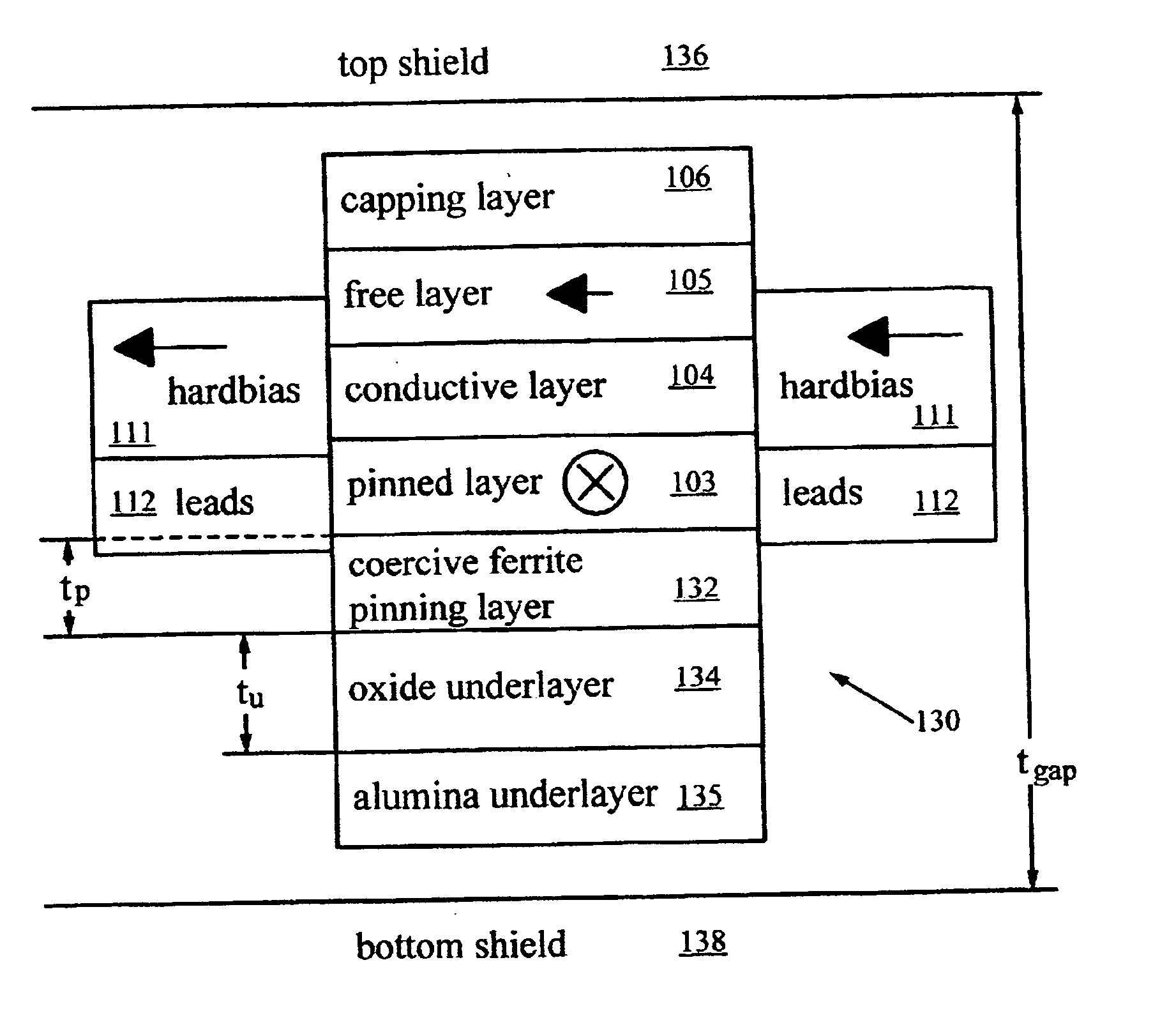
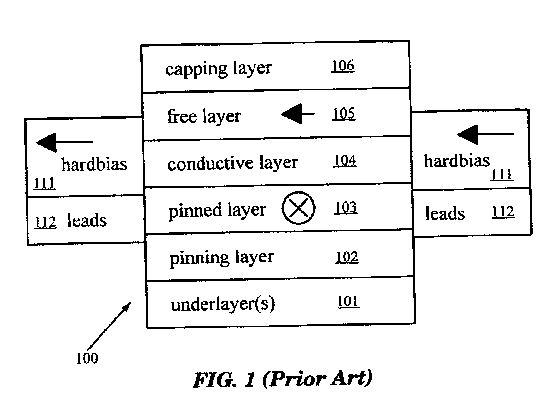
[0042]FIG. 3A illustrates the underlayer of the present invention in a simple spin valve magnetoresistive sensor 130, shown in cross section. Sensor 130 contains substantially the same layer structure as prior art spin valve MR sensor 100, including pinned layer 103, conductive layer 104, free layer 105, capping layer 106, hard-bias material 111, and leads 112. It also contains a coercive ferrite pinning layer 132 of thickness tp and an oxide underlayer 134 of thickness tu. As explained below, oxide underlayer 134 directs the growth of coercive ferrite layer 132, thereby increasing its coercivity and thermal stability. As a result, coercive ferrite layer 132 can be made very thin; tp is between 1 and 30 nm; tu is between 1 and 30 nm. Sensor 130 fits in a gap of thickness tgap between a top shield 136 and a bottom shield 138 of a magnetic read head. Sensor 130 also typically contains an insulating underlayer 135 such as alumina.

[0043] Underla...

second embodiment

[0067] Hard Biasing for Spin-Valves and Magnetic Tunnel Junctions

[0068] This embodiment of the invention relates to exchange-coupled structures such as spin valves and magnetic tunnel junctions (MTJs). MTJs have been proposed for magnetic memory cells (MRAM) and magnetoresistive read heads. A magnetic tunnel junction consists of two ferromagnetic layers separated by an insulating non-magnetic tunneling barrier. The barrier is thin enough that quantum-mechanical tunneling occurs between the ferromagnetic layers. Since the tunneling probability is spin-dependent, the tunneling current is a function of the relative orientation of the two magnetic layers. Thus a MTJ can serve as a MR sensor. For a constant applied voltage, the resistance of the MTJ changes from a low to a high state as the relative orientation of the two ferromagnetic layers changes. Depending upon the electronic band structure of the two ferromagnetic layers, either parallel or antiparallel alignment of the ferromagnet...


PUM

PropertyMeasurementUnit
thicknessaaaaaaaaaa
thicknessaaaaaaaaaa
thicknessaaaaaaaaaa

Abstract

An exchange-coupled magnetic structure includes a ferromagnetic layer, a coercive ferrite layer, such as cobalt-ferrite, for biasing the magnetization of the ferromagnetic layer, and an oxide underlayer, such as cobalt-oxide, in proximity to the coercive ferrite layer. The oxide underlayer has a lattice structure of either rock salt or a spinel and exhibits no magnetic moment at room temperature. The underlayer affects the structure of the coercive ferrite layer and therefore its magnetic properties, providing increased coercivity and enhanced thermal stability. As a result, the coercive ferrite layer is thermally stable at much smaller thicknesses than without the underlayer. The exchange-coupled structure is used in spin valve and magnetic tunnel junction magnetoresistive sensors in read heads of magnetic disk drive systems. Because the coercive ferrite layer can be made as thin as 1 nm while remaining thermally stable, the sensor satisfies the narrow gap requirements of high recording density systems.

Description

RELATED APPLICATIONS [0001] This is a divisional application of the application bearing Ser. No. 09 / 841,942 filed Apr. 24, 2001 which has been allowed. Another divisional of the same parent is 10 / 931,315 filed on Aug. 31, 2004.FIELD OF THE INVENTION [0002] This invention relates generally to magnetic devices such as spin valve magnetoresistive (MR) sensors and magnetic tunnel junctions. More particularly, it relates to exchange-coupled magnetic structures containing underlayers that enhance the stability of coercive ferrite layers used to bias the magnetic moment of adjacent ferromagnetic layers. BACKGROUND ART [0003] Computer systems generally use auxiliary memory storage devices having media on which data can be written and from which data can be read for later use. A direct access storage device (disk drive) incorporating rotating magnetic disks is commonly used for storing data in magnetic form on the disk surfaces. Data are recorded on concentric, radially spaced tracks on the ...

Claims


Application Information

Patent Timeline
Patent Type & Authority Applications(United States)
IPC IPC(8): G01R33/09G11B5/012G11B5/39H01F10/32
CPCB82Y10/00B82Y25/00G01R33/093H01F10/3277G11B5/3903G11B5/3967G11B5/012
Inventor CAREY, MATTHEW JOSEPHFULLERTON, ERIC EDWARDGURNEY, BRUCE ALVINLE, THAIMAAT, STEFANRICE, PHILIP MILTON
Owner CAREY MATTHEW JOSEPH
Why Eureka
Try Eureka