Constant voltage circuit

Inactive Publication Date: 2005-02-17
RICOH ELECTRONIC DEVICES CO LTD
View PDF5 Cites 27 Cited by
  • Summary
  • Abstract
  • Description
  • Claims
  • Application Information

AI Technical Summary

Benefits of technology

[0021] According to the present invention, a constant voltage circuit may be provided with an overcurrent protection circuit with the limiting characteristic of an output voltage and curr

Problems solved by technology

Therefore, when a bias current set by the PMOS transistor M53 is reduced to decrease current consumption of the differential amplifier circuit, the speed of response of the differential amplifier circuit is reduced so that it is difficult to perform phase compensation.
Inappropri

Method used


Image

  • Constant voltage circuit
  • Constant voltage circuit
  • Constant voltage circuit

Examples


first embodiment

[0041] [First Embodiment]

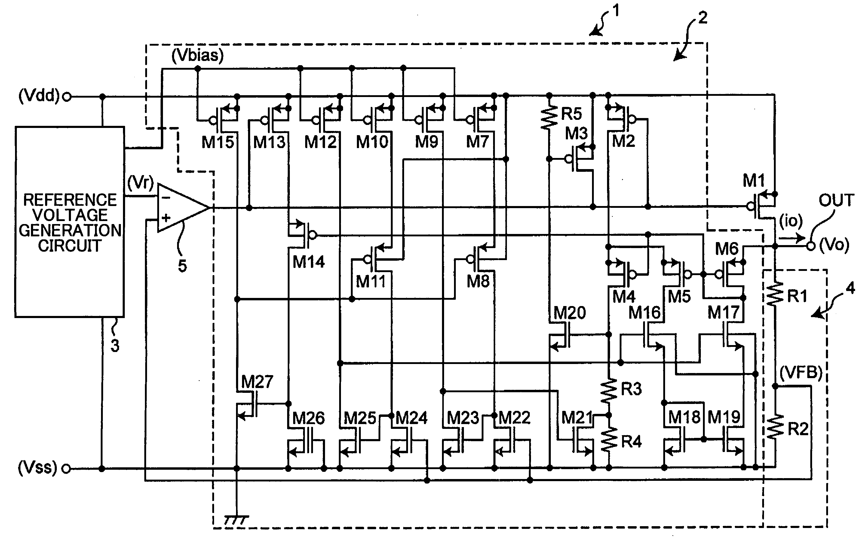
[0042]FIG. 3 is a circuit diagram showing a constant voltage circuit 1 according to a first embodiment of the present invention.

[0043] Referring to FIG. 3, the constant voltage circuit 1 controls an output current io output from an output terminal OUT so that an output voltage Vo output from the output terminal OUT remains constant at a predetermined voltage. The constant voltage circuit 1 includes an overcurrent protection circuit 2 for the output current io. The overcurrent protection circuit 2 operates so that the relationship between the output voltage Vo and the output current io has a characteristic approximating the conventional foldback characteristic.

[0044] The constant voltage circuit 1 includes the overcurrent protection circuit 2, a reference voltage generation circuit 3 generating and outputting a predetermined reference voltage Vr, an output voltage detection circuit 4 dividing the output voltage Vo between resistors R1 and R2 and outputting ...

second embodiment

[0086] [Second Embodiment]

[0087]FIG. 13 is a circuit diagram showing a constant voltage circuit la according to a second embodiment of the present invention.

[0088] Referring to FIG. 13, the constant voltage circuit 1a controls an output current io output from an output terminal OUT so that an output voltage Vo output from the output terminal OUT remains constant at a predetermined voltage. The constant voltage circuit 1a includes an overcurrent protection circuit 2a for the output current io. The overcurrent protection circuit 2a operates so that the relationship between the output voltage Vo and the output current io has a characteristic approximating the conventional foldback characteristic.

[0089] The constant voltage circuit 1a includes the overcurrent protection circuit 2a, a reference voltage generation circuit 3a generating and outputting a predetermined reference voltage Vr, an output voltage detection circuit 4a dividing the output voltage Vo between resistors R71 and R72 ...

third embodiment

[0105] [Third Embodiment]

[0106] The first and second embodiments may be combined as one, which is shown as a third embodiment.

[0107]FIG. 16 is a circuit diagram showing part of a constant voltage circuit 1b according to the third embodiment of the present invention. In FIG. 16, the same elements as those of FIGS. 3 and 13 are referred to by the same numerals, and a description thereof is omitted. A description is given below of the differences from FIG. 3, and FIG. 16 shows a circuit part different from FIG. 3.

[0108] In FIG. 16, the differences from FIG. 3 lie in that the resistor R3 of FIG. 3 is replaced with the series circuit of the resistors R73 through R75 of FIG. 13 and that the PMOS transistor M3, the NMOS transistor M20, and the resistor R5 are replaced with the PMOS transistor M73, the NMOS transistor M79, and the resistor R76 of FIG. 13. As a result of this change, the overcurrent protection circuit 2 of FIG. 3 is changed to an overcurrent protection circuit 2b in the th...


PUM


Abstract

A constant voltage circuit is disclosed that includes an output control transistor and an overcurrent protection circuit. The overcurrent protection circuit includes a proportional current generation circuit part, a current division circuit part, a division ratio control circuit part, a current-voltage conversion circuit part, and an output current control circuit part. When the output voltage of the current-voltage conversion circuit part reaches a predetermined voltage, the output current control circuit part prevents an increase in the output current of the output control transistor so as to reduce a voltage output from an output terminal. When the voltage output from the output terminal is reduced to a predetermined limit voltage, the division ratio control circuit part changes the division ratio of the current division circuit part so that a current supplied to the current-voltage conversion circuit part increases so as to reduce the output current of the output control transistor.

Description

BACKGROUND OF THE INVENTION [0001] 1. Field of the Invention [0002] The present invention relates generally to constant voltage circuits with an overcurrent protection circuit, and more particularly to a constant voltage circuit with an overcurrent protection circuit having a foldback characteristic. [0003] 2. Description of the Related Art [0004]FIG. 1 is a circuit diagram showing a conventional constant voltage circuit 100 having an overcurrent protection circuit with a foldback characteristic. In the following, a description of a constant voltage generation operation in the constant voltage circuit 100 is omitted, and a description is given of the overcurrent protection circuit with a foldback characteristic. [0005] Referring to FIG. 1, the source and the gate of a p-channel MOS (PMOS) transistor M42 are connected to the source and the gate, respectively, of a PMOS transistor M41 forming a driver transistor controlling an output current iout. A drain current output from the drain...

Claims


Application Information

Patent Timeline
IPC IPC(8): G05F1/573
CPCG05F1/573
Inventor NAGATA, TOSHIHISAAGARI, HIDEKIYOSHII, KOHJI
Owner RICOH ELECTRONIC DEVICES CO LTD
Why Eureka
Try Eureka