Fixed-focus camera module and associated method of assembly

a technology of fixed-focus camera modules and assembly methods, which is applied in the direction of camera focusing arrangement, printers, instruments, etc., can solve the problems of limiting the ability to use low-cost construction materials, labor-intensive assembly processes of conventional digital camera modules, and high cost of materials

Inactive Publication Date: 2005-02-17
APTINA IMAGING CORP
View PDF8 Cites 208 Cited by
  • Summary
  • Abstract
  • Description
  • Claims
  • Application Information

AI Technical Summary

Benefits of technology

[0008] One embodiment of the present invention provides a fixed-focus camera module including an image sensor, a lens for focusing an image onto the image sensor, and a positioning structure for maintaining an alignment of the lens and image sensor. The alignment provides a desired image quality of the image focussed onto the image sensor. The positioning structure includes a first unthreaded member coupled to the lens and a second unthreaded member coupled to the image sensor. One of the first and the second members is configured to be inserted into the other of the members to provide an adjustable relative position of the lens and the image sensor.

Problems solved by technology

Conventional assembly processes for digital camera modules tend to be labor-intensive.
Because traditional focusing processes are manual operations, and because human operators cannot reliably achieve a sufficient focus without mechanical assistance, conventional camera modules typically include high-precision structural features that facilitate setting the proper focus, such as a lens assembly that attaches to the camera housing with screw threads.
The use of built-in structural features, such as screw threads, for establishing a proper focus for each manufactured digital camera module, limits the ability to use low cost construction materials.
Only certain types of materials can support machining and / or high precision molding, and such materials are typically more expensive than the materials that are unable to support such processes.
For parts having machined features, the process of machining adds costs to the parts.
Moreover, particulate residue from the machining process can remain on the parts and can potentially settle on the image sensor, thereby partially obstructing it.
For parts molded with high precision, materials of relatively high cost are typically required, as compared to materials for low-precision molded parts.
However, such materials are costly compared to conventional lens materials.

Method used


Image

  • Fixed-focus camera module and associated method of assembly
  • Fixed-focus camera module and associated method of assembly
  • Fixed-focus camera module and associated method of assembly

Examples


Embodiment Construction

[0019] In the following detailed description of the preferred embodiments, reference is made to the accompanying drawings which form a part hereof, and in which is shown by way of illustration specific embodiments in which the invention may be practiced. It is to be understood that other embodiments may be utilized and structural or logical changes may be made without departing from the scope of the present invention. The following detailed description, therefore, is not to be taken in a limiting sense, and the scope of the present invention is defined by the appended claims.

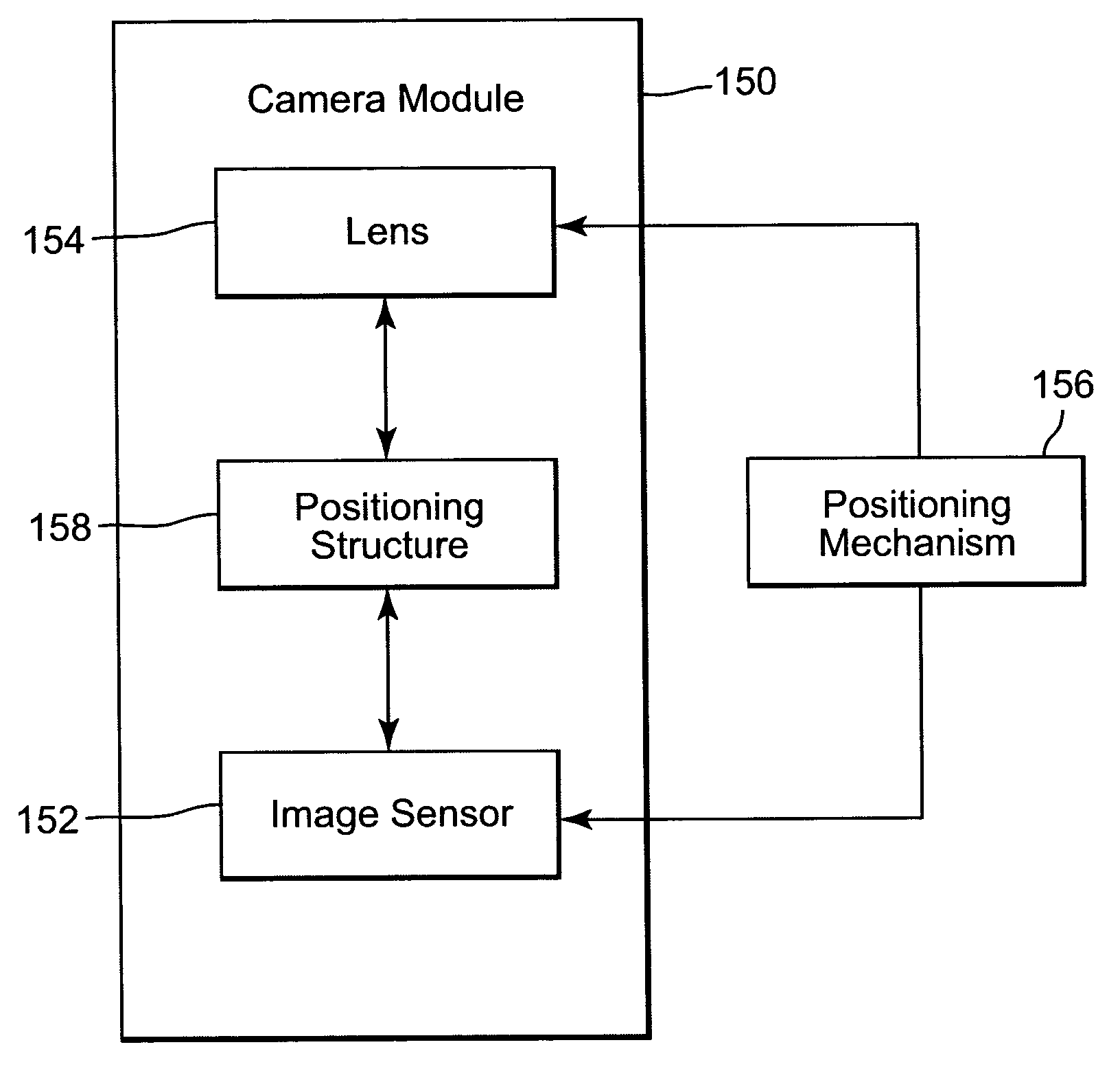
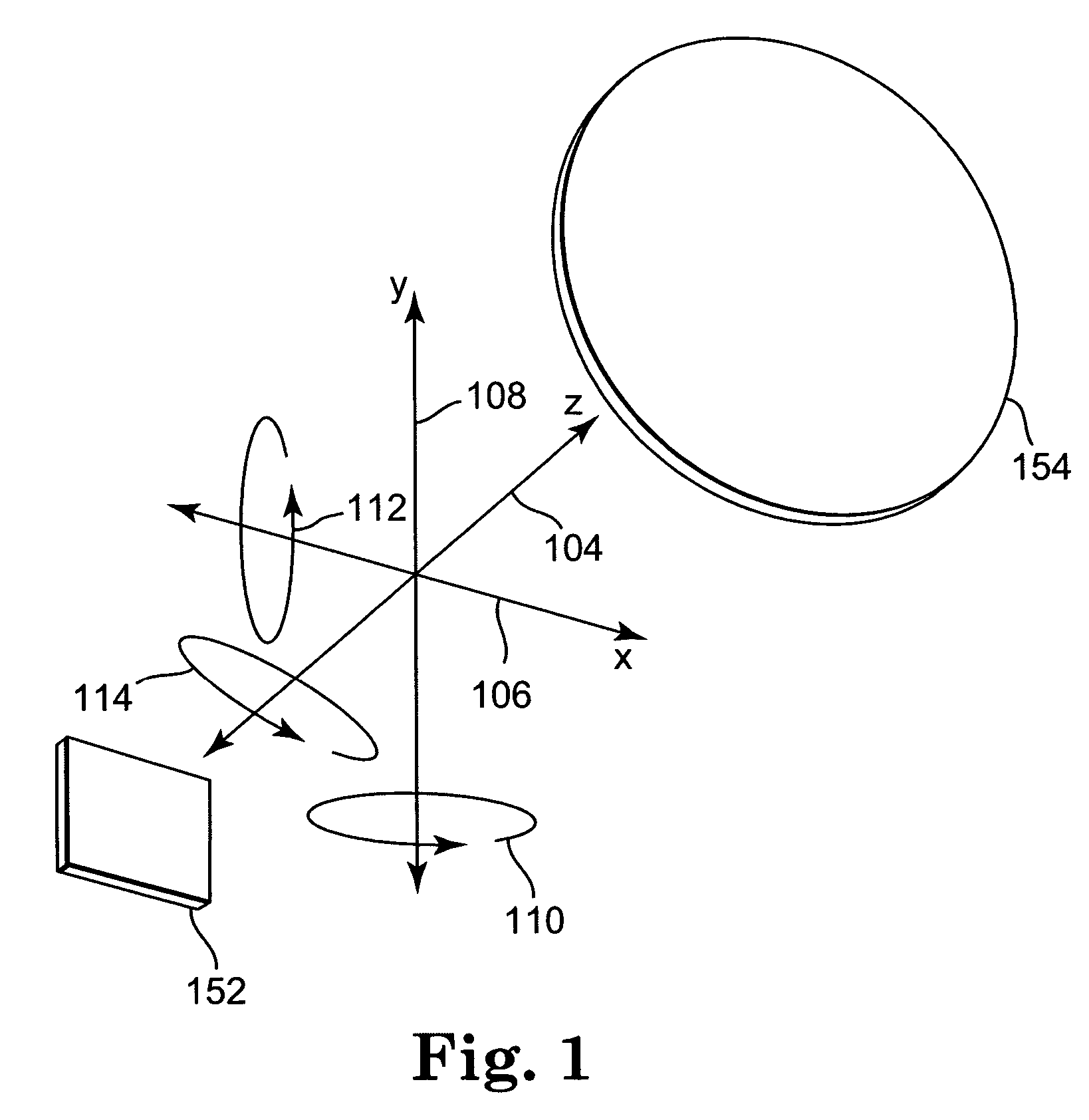
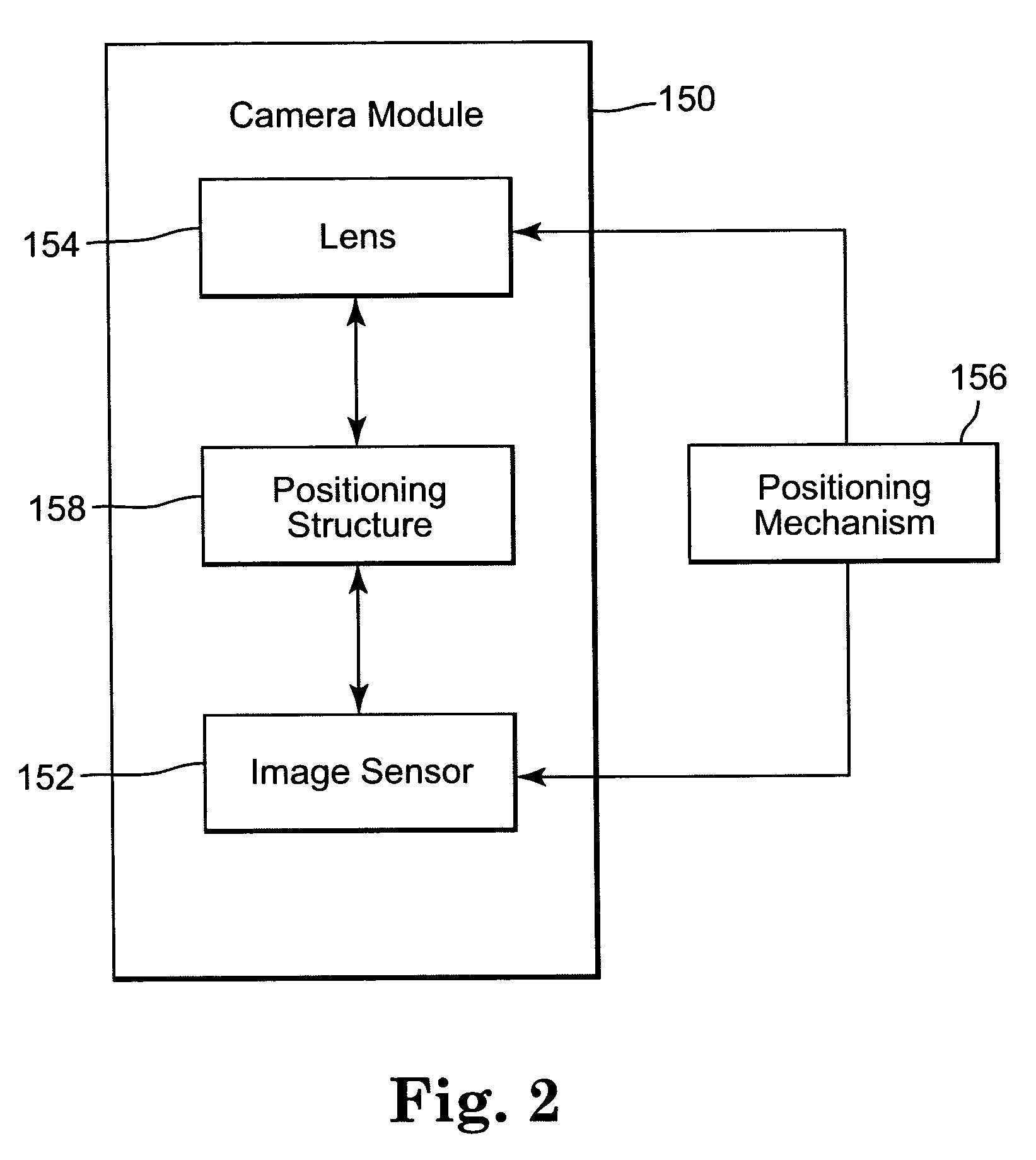
[0020] Part of the assembly process of fixed-focus digital camera modules involves achieving a proper focus of the image projected onto the image sensor. Focusing is typically accomplished by positioning the lens relative to the image sensor. FIG. 1 is a diagram illustrating various ways of positioning an image sensor 152 and a lens 154. Typically, the positioning is along five degrees of freedom: translational...


PUM


Abstract

A fixed-focus camera module includes an image sensor, a lens for focusing an image onto the image sensor, and a positioning structure for maintaining an alignment of the lens and image sensor. The alignment provides a desired image quality of the image focussed onto the image sensor. The positioning structure includes a first unthreaded member coupled to the lens and a second unthreaded member coupled to the image sensor. One of the first and the second members is configured to be inserted into the other of the members to provide an adjustable relative position of the lens and the image sensor.

Description

THE FIELD OF THE INVENTION [0001] The present invention relates generally to camera modules, and more particularly to a fixed-focus camera module having a positioning structure for maintaining an alignment of the lens and image sensor. BACKGROUND OF THE INVENTION [0002] Digital camera technology is being used in an increasing variety of mass-produced applications, and in increasing production volumes. For example, miniature fixed-focus digital camera modules are being incorporated into consumer products such as portable telephones and personal digital assistants (PDA's). Given the new high volume applications for digital camera modules, it is desirable to reduce their per unit material and assembly costs. [0003] Digital camera modules generally include a lens for focusing incoming light onto an image sensor that detects an image and converts it into an electrical signal representation. An image processor is employed to further manipulate the image signal into an image of a suitable ...

Claims


Application Information

Patent Timeline
Patent Type & Authority Applications(United States)
IPC IPC(8): G03B13/32
CPCG03B13/32
Inventor DEMONTE, FRANK J.
Owner APTINA IMAGING CORP
Why Eureka
Try Eureka