Hub for a passive optical network hub

a technology of optical network and hub, applied in the field of passive optical network, can solve the problem of increasing the cost of the head end

Active Publication Date: 2005-02-17
GOOGLE TECH HLDG LLC
View PDF11 Cites 57 Cited by
  • Summary
  • Abstract
  • Description
  • Claims
  • Application Information

AI Technical Summary

Problems solved by technology

One disadvantage of this arrangement, however, is that as demand continues to grow, the increasing number of high power amplifier modules that are required makes the head end increasingly expensive.

Method used


Image

  • Hub for a passive optical network hub
  • Hub for a passive optical network hub
  • Hub for a passive optical network hub

Examples


Embodiment Construction

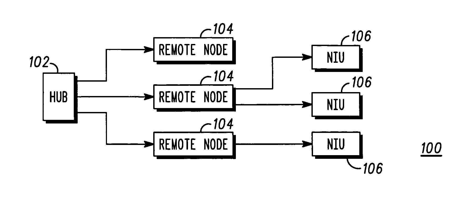
[0025] The present inventor has recognized that the hub of a passive optical network (PON) can be reduced in cost by replacing the conventional EDFAs that serve as the high power amplifiers with cladding pumped EDFAs. As explained below, cladding pumped EDFAs can use less expensive, multimode pump sources instead of the more expensive single mode pump sources required by conventional EDFAs.

[0026] Cladding pumped EDFAs overcome a problem that arises in a conventional EDFA when attempting to increase their output power by increasing the pump power with which they are supplied. Generally, the pump source is a laser diode. A common way of increasing the output power of the laser diode is to increase its emitting area. This makes it possible to increase the power without increasing the power density at the output facet of the device. Unfortunately, the resulting broad-area laser diode is multimode, and its output is no longer sufficiently coherent to be coupled into a single-mode fiber....


PUM


Abstract

A hub for use in a passive optical network (PON) includes a transmission fiber on which an information-bearing optical signal is received, a double-cladded, rare-earth doped fiber located along the transmission fiber for imparting gain to the information-bearing optical signal, and a combiner having an output coupled to the transmission fiber and a plurality of inputs. The output is coupled to the transmission fiber such that optical energy at pump energy wavelengths but not signal wavelengths are communicated therebetween. At least one pump source is optically coupled to one of the inputs of the combiner for providing optical pump energy to the double-cladded, rare-earth doped fiber. An optical splitter is also provided. The optical splitter has an input coupled to the transmission fiber for receiving an amplified, information-bearing optical signal and a plurality of outputs for directing portions of the amplified, information-bearing optical signal to remote nodes in the PON.

Description

FIELD OF THE INVENTION [0001] The present invention relates generally to passive optical networks, and more particularly to a passive optical network having a hub or head end that employs a cladding pumped erbium doped optical amplifier. BACKGROUND OF THE INVENTION [0002] Optical networks that employ passive architectures are often referred to as Passive Optical Networks (PONs). Such networks use some form of passive component such as an optical star coupler or a static wavelength router and thus do not have any active switching elements. A primary advantage of a PON is its reliability, ease of maintenance and the fact that the field-deployed network does not need to be powered. Accordingly, PONs are often used as access networks by cable TV and telecommunications providers for the purpose of distributing their services from their facility to the customer premises (e.g., a home or business). [0003]FIG. 1 shows the architecture of a PON in its most generalized form. The PON 100 inclu...

Claims


Application Information

Patent Timeline
Patent Type & Authority Applications(United States)
IPC IPC(8): H04B10/17H04B10/272
CPCH04B10/2939H04B10/272
Inventor RAMACHANDRAN, MANIJASTI, CHANDRA SEKHAR
Owner GOOGLE TECH HLDG LLC
Why Eureka
Try Eureka