Automated quality control protocols in a multi-analyzer system

a multi-analyzer and quality control technology, applied in the field of automated clinical sample handling worksystems, can solve the problems of increasing complexity associated with performing the proper quality control procedures within the multi-analyzer automated clinical analyzer system, affecting so as to improve the overall reliability of robotic insertion. the effect of improving the interfa

Active Publication Date: 2005-02-17
SIEMENS HEALTHCARE DIAGNOSTICS INC
View PDF23 Cites 81 Cited by
  • Summary
  • Abstract
  • Description
  • Claims
  • Application Information

AI Technical Summary

Benefits of technology

The unique design of an sample tube carrier associated with method for automatically operating an sample handling system the improves its interface with any robotic devices of a clinical laboratory's automated sample handling system and improves the overall reliability of robotic insertion and retrieval of a sample tube from the sample tube carrier.

Problems solved by technology

Such improvements, while necessary in themselves, may be hampered if sufficient corresponding advances are not made in the areas of pre-analytical sample preparation and handling operations like sorting, batch preparation, centrifugation of sample tubes to separate sample constituents, cap removal to facilitate fluid access, and the like.
Although these prior art systems have advanced sample handling and processing throughput, what has not been addressed is the increasing complexity associated with performing the proper quality control procedures within multi-analyzer automated clinical analyzer system.
In particular, Laboratory Automation Systems typically have not dealt with the impact of Quality Control procedures on the analytical clinical analyzers they automate.
However, quality control procedures that call for running a calibration or control assay every “n” assays present a significant challenge in a multi-analyzer automated clinical analyzer system.
If, for example, four analyzers are each performing ten assays that require a calibration or control assay be conducted every 24 sample assays, the conveyor system linking the analyzers together will become highly concentrated with calibration or control liquids, adversely affecting overall system throughput.

Method used


Image

  • Automated quality control protocols in a multi-analyzer system
  • Automated quality control protocols in a multi-analyzer system
  • Automated quality control protocols in a multi-analyzer system

Examples


example

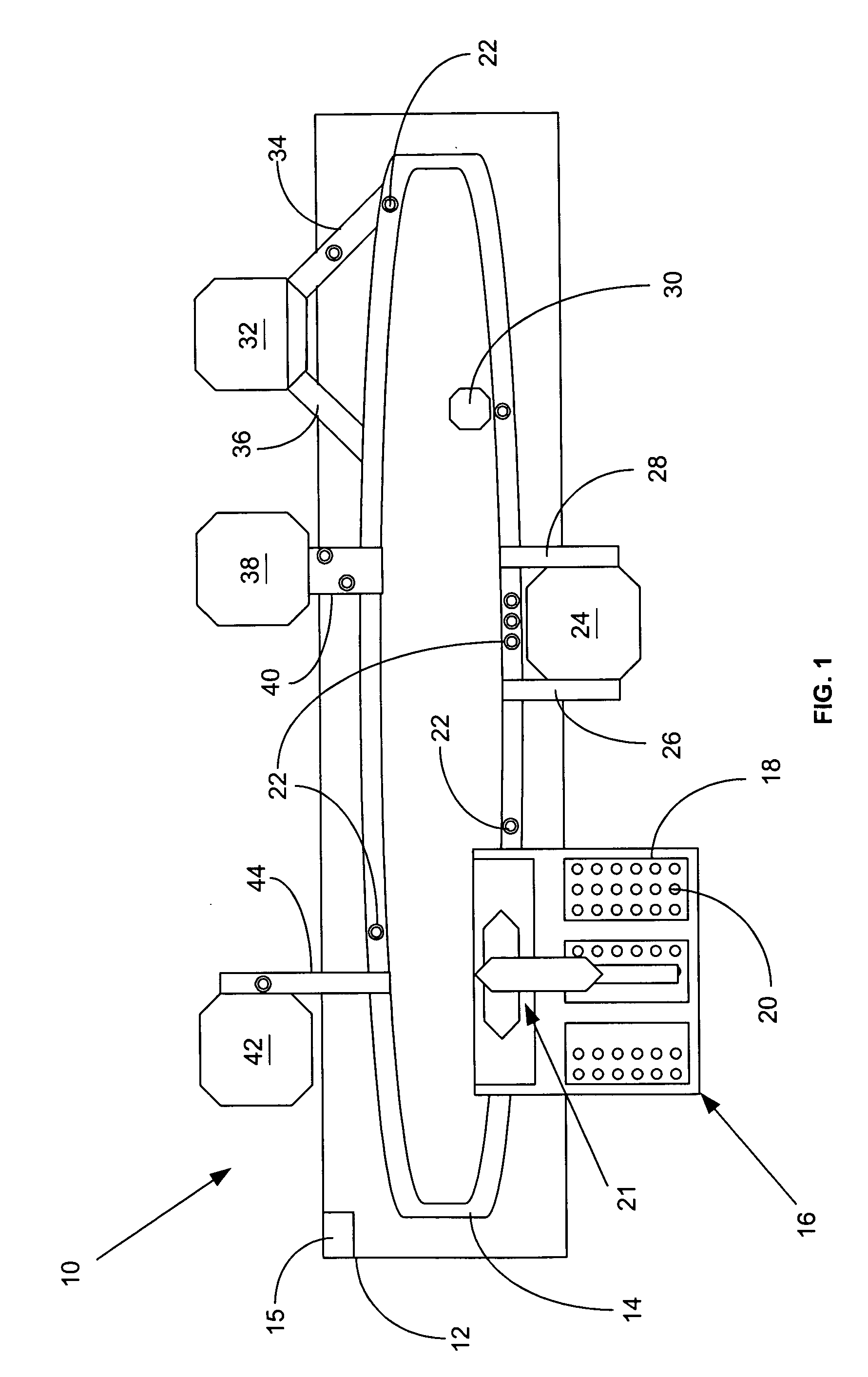
The following Example is presented a non-limiting illustration of the present method for automatically ensuring that assays specified to be conducted on samples in incoming sample containers 20 are performed only on an analyzer 32, 38, and 42 which is in compliance with the set of assay defined rules associated with the assays to be conducted.

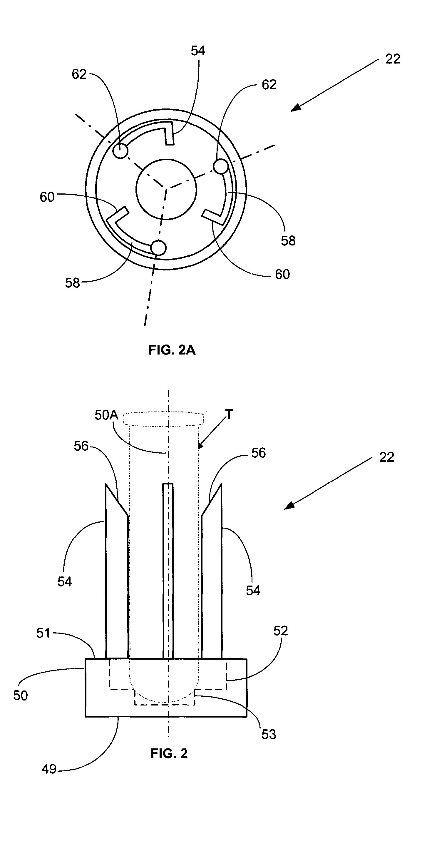
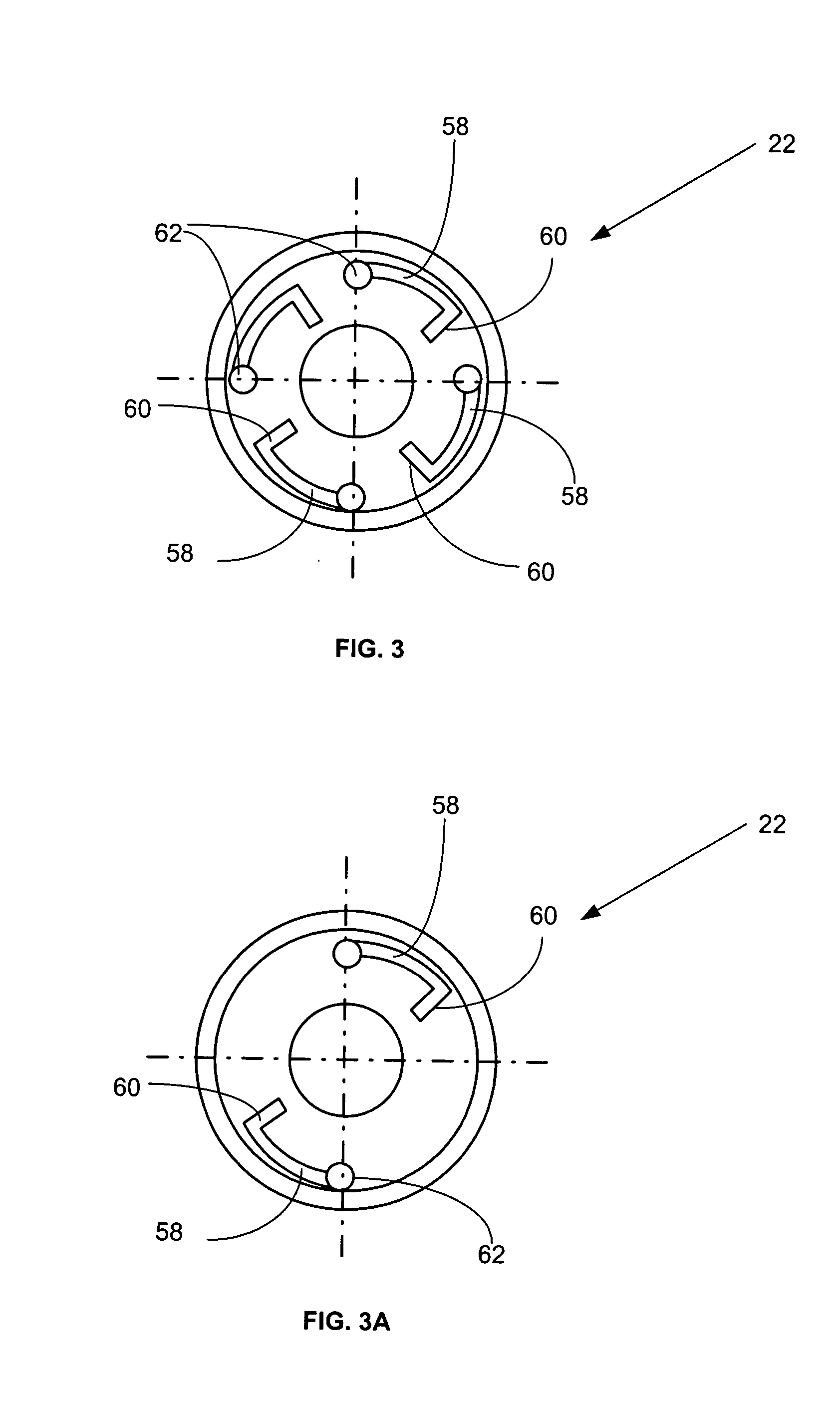
Twelve sample containers 20 originally contained in a sample rack 18 are individually removed by sample tube loading / unloading station 16 from sample rack 18 and placed into individual sample tube carriers 22. Based upon sample container identification indicia, such as a bar code, conveyor track 14 is controlled by CPU 15 and laboratory LIS to transport individual sample tube containers 20 as required by the prescribed assay(s) to be conducted on the sample therein to an automated centrifuge 24 and / or to an automated tube de-capper 30 for automatically removing caps from capped sample containers 20.

CPU 15 and / or laboratory LIS compare the ...


PUM

PropertyMeasurementUnit
concentrationaaaaaaaaaa
buffering capacityaaaaaaaaaa

Abstract

A method for automatically operating a sample handling system and associated analyzers to conduct assays on a number of patient samples by comparing the assays to be conducted with a set of assay defined rules, subdividing the analyzers into analyzers which are in compliance with the assay defined rules and analyzers not in compliance with the set of assay defined rules; thereafter, operating the system to supply patient samples to analyzers in compliance or operating the system so as to bring at least one analyzer into compliance with the assay defined rules and supplying patient samples to such an analyzer.

Description

FIELD OF THE INVENTION The present invention relates to an automated clinical sample handling worksystem with two or more independent analyzers having samples supplied thereto by an automated conveyor system. More particularly, the present invention relates to a method for automating the processes involved in performing quality control procedures within such an automated clinical sample handling worksystem. BACKGROUND OF THE INVENTION Clinical diagnostic analyzers are being developed with increasing levels of complexity and sophistication in order to fully automated the performance of chemical assays and immunoassays of biological fluid samples such as urine, blood serum, plasma, cerebrospinal liquids and the like, these fluid samples almost universally being contained in open or capped sample tubes. Generally, chemical reactions between an analyte in a patient's biological sample and reagents used during performing the assay result in generating various signals that can be measur...

Claims


Application Information

Patent Timeline
Patent Type & Authority Applications(United States)
IPC IPC(8): G01N35/00
CPCG01N35/00G01N35/00623G01N35/00693G01N35/00712G01N35/0092G01N35/04Y10T436/11Y10T436/2575Y10T436/113332Y10T436/114998Y10T436/114165Y10T436/115831G01N2035/0467
Inventor MILLER, KERRY LYNN
Owner SIEMENS HEALTHCARE DIAGNOSTICS INC
Why Eureka
Try Eureka