Clamping arrangement for receiving a saw blade in multiple orientations

a technology of clamping arrangement and saw blade, which is applied in the field of clamping arrangement of saw blades for power tools, can solve the problems of loosing the set screw, inability to quickly and easily remove saw blades which become worn or fractured, and inability to quickly and easily install and remove saw blades. the effect of quick and easy installation and removal

Inactive Publication Date: 2005-02-24
BLACK & DECKER INC
View PDF63 Cites 25 Cited by
  • Summary
  • Abstract
  • Description
  • Claims
  • Application Information

AI Technical Summary

Benefits of technology

[0008] The present invention provides various embodiments to saw blade clamping arrangements for reciprocating power tools that overcome disadvantages associated with the prior art. More particularly, the present invention provides a new and improved saw blade clamping arrangement for a power recipro

Problems solved by technology

While this conventional manner of saw blade attachment has proven to be generally satisfactory and commercially successful, it is not without inherent disadvantages.
For example, power reciprocating saws are subject to high vibration forces during operation which frequently result in loosening of the set screw.
If the set screw does not remain sufficiently tightened, the saw blade may become disengaged from the drive shaft.
An additional disadvantage with the conventional mounting of saw blades to reciprocating drive shafts relates to an inability to quickly and easily remove saw blades which become worn or fractured.
As a result, breakage due to the forces encountered during typical use is not an uncommon occurrence.
A further disadvantage of conventional blade clamping arrangements is the necessity for a separate tool such as a wrench for fixation and removal of the saw blade.
However, all of these previous attempts are sub

Method used


Image

  • Clamping arrangement for receiving a saw blade in multiple orientations
  • Clamping arrangement for receiving a saw blade in multiple orientations
  • Clamping arrangement for receiving a saw blade in multiple orientations

Examples


first embodiment

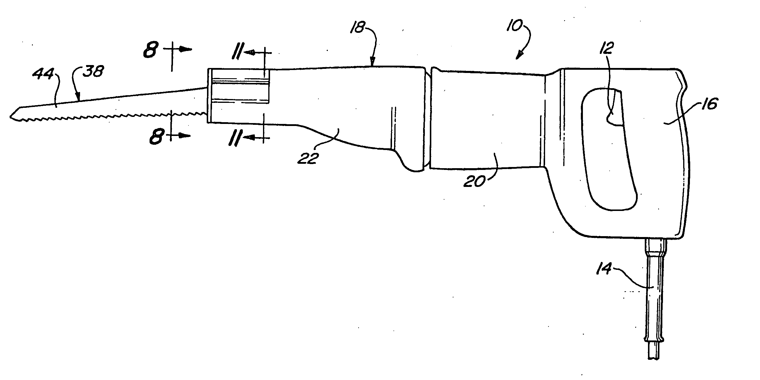
[0149] Turning now to FIGS. 20-31 of the drawings, a saw blade clamping arrangement 56″ constructed in accordance with the third preferred embodiment of the present invention will now be described. Again, components similar to those identified with respect to the first embodiment will be designated in the drawings with corresponding reference numerals. As with the first and second preferred embodiments, saw blade clamping arrangement 56″ is operative for use with power tool 10 such as reciprocating saw or other tool including a reciprocating drive shaft 30.

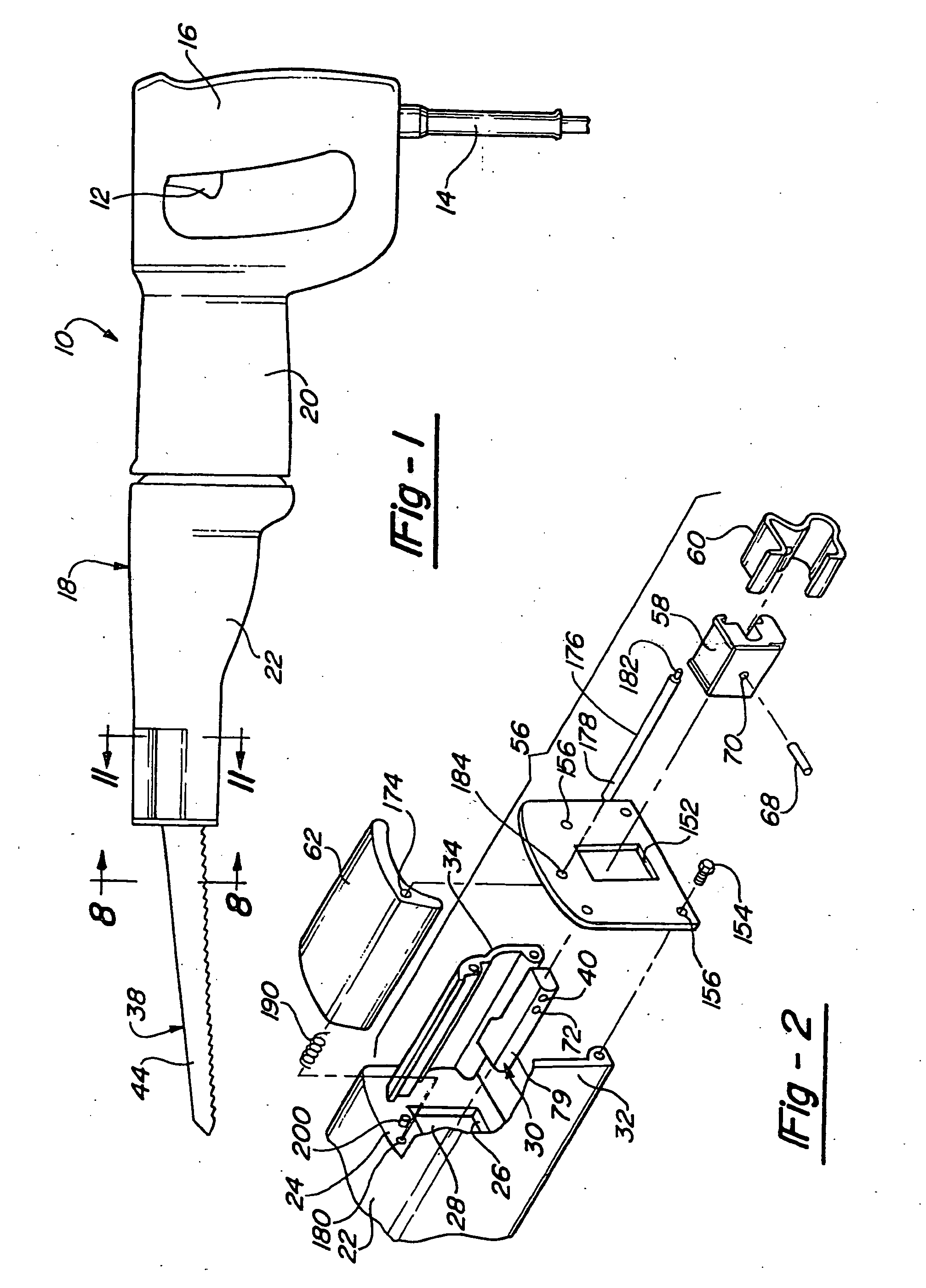
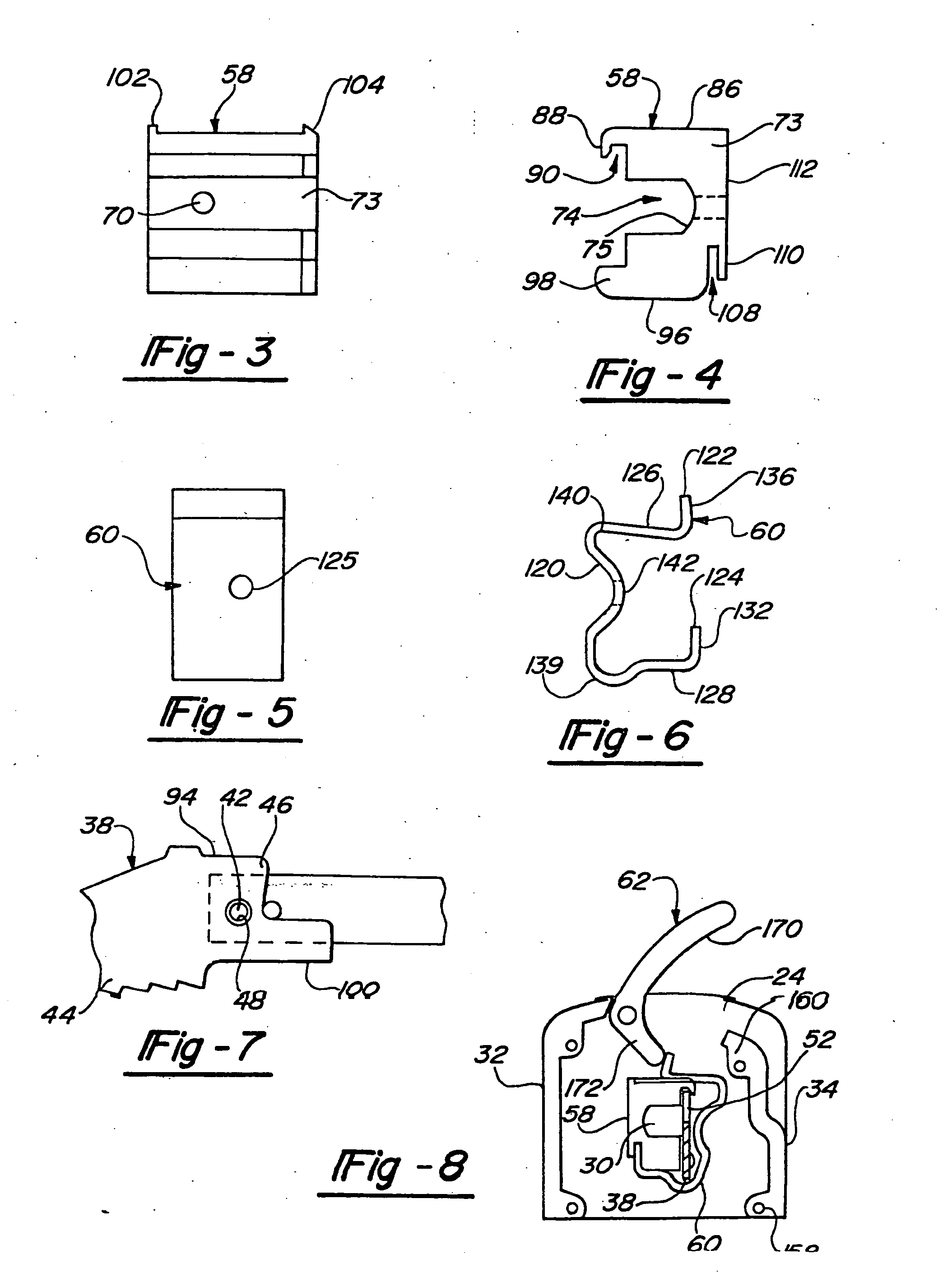
[0150] As with the first preferred embodiment of the present invention, saw blade clamping arrangement 56″ of the third preferred embodiment includes a support member 58, a biasing member 60 and an actuation member 62. Saw blade clamping arrangement 56″ of the third preferred embodiment departs from the first preferred embodiment in that it additionally incorporates a locking member 310 operatively interconnect saw blade 38 to dri...

third embodiment

[0176] As with the prior embodiments, the clamping arrangement 500 includes a release lever 532 which functions to translate the slider 504 from the first position to the second position. In a normal position (as shown in FIG. 41), the release lever 532 is spaced apart from a flange 536 of the slider 504. It will be appreciated that the release lever 532 does not reciprocate with the drive shaft 30 of the tool 10. The release lever 532 is movable (i.e., rotatable) to a second position (as shown in FIG. 48). In this second position, the release lever 130 displaces the slider 504 downward to its second position and thereby permits removal and replacement of the saw blade 38 in the manner discussed above. The slider 504 is biased upward (as shown in FIGS. 47 and 49) to its first position by a biasing member 538 (shown in FIG. 43B). The biasing member 538 is preferably a spring 538. A spring identical in construction and function is shown in FIG. 23 in connection with the present invent...


PUM

PropertyMeasurementUnit
Forceaaaaaaaaaa
Angleaaaaaaaaaa
Shapeaaaaaaaaaa

Abstract

A saw blade clamping arrangement for a power tool including a drive shaft and a saw blade releasably interconnected with the drive shaft for reciprocating motion along a longitudinal axis. The saw blade clamping arrangement includes a support mechanism interconnected with the drive shaft, the support mechanism configured to selectively receive the saw blade in first and second orientations, an actuator mounted on the drive shaft and rotatable relatively to the drive shaft between an engaged position and a disengaged position, the actuator including first and second locking cam surfaces, and first and second locking members operatively associated with the actuator, and movable between a locked position that selectively locks the blade to the corresponding first and second orientations and an unlocked position that releases the blade. The first and second locking members including first and second follower surfaces driven by the respective first and second locking cam surfaces.

Description

CROSS-REFERENCE TO RELATED APPLICATION [0001] This is a continuation-in-part application of U.S. Ser. No. 10 / 337,232 filed on Jan. 6, 2003, which is continuation-in-part application of U.S. Ser. No. 09 / 955,374, filed Sep. 17, 2001 (now U.S. Pat. No. 6,502,317), which is a continuation of U.S. Ser. No. 09 / 416,819, filed Oct. 12, 1999 (now U.S. Pat. No. 6,295,736), which is a continuation-in-part application of U.S. Ser. No. 09 / 057,788 filed Apr. 9, 1998 (now U.S. Pat. No. 6,023,848), which is a continuation-in-part application of U.S. Ser. No. 08 / 881,091 filed Jun. 24, 1997 (now U.S. Pat. No. 6,009,627), which is a continuation-in-part application of U.S. Ser. No. 08 / 744,023 filed Nov. 5, 1996 (now U.S. Pat. No. 5,794,352), which is a continuation-in-part application of U.S. Ser. No. 08 / 504,050, filed Jun. 9, 1995 (now U.S. Pat. No. 5,647,133). The disclosures of the above applications are incorporated herein by reference.FIELD OF THE INVENTION [0002] The present invention relates in...

Claims


Application Information

Patent Timeline
IPC IPC(8): B23D49/16B23D51/10
CPCB23D49/167Y10T279/17769B23D51/10Y10T83/9481
Inventor BIGDEN, JONATHAN D.ANDERSON, JOSEPH D.WATTENBACH, BRIAN P.O'BANION, MICHAEL
Owner BLACK & DECKER INC
Why Eureka
Try Eureka