Heating cooking device

a technology of cooking device and heating chamber, which is applied in the field of cooking oven, can solve problems such as high-level decomposition, and achieve the effect of efficient heating of air and efficient heating of air

Inactive Publication Date: 2005-02-24
SHARP KK
View PDF13 Cites 44 Cited by
  • Summary
  • Abstract
  • Description
  • Claims
  • Application Information

AI Technical Summary

Benefits of technology

[0021] An object of the present invention is to provide a cooking oven that permits a catalyst to function satisfactorily and that can decompose greasy fumes and odor substances with high efficiency.
[0022] To achieve the above object, according to the present invention, a cooking oven is constructed as follows. The cooking oven has a blowout port and a suction port for passage of a hot air stream provided inside a cooking chamber and has a blower and a heat source for producing the hot air stream provided outside the cooking chamber so as to produce a circulated hot air stream inside the cooking chamber so that foods are cooked with heat by the circulated air stream. In this cooking oven, a catalyst block for decomposing substances released from foods and a heat source for heating the catalyst block are arranged inside the duct through which the hot air stream is fed to the blowout port. The heat source is so arranged as to face a plurality of faces of the catalyst block. With this construction, the catalyst block receives radiant heat from a plurality of directions, and thus quickly reaches the temperature that permits the catalyst to function. This permits the catalyst to start to function at an early stage. Moreover, of the plurality of faces of the catalyst block, one is made to face in the direction from which the circulated air stream blows. Thus, the circulated air stream heated by the heat source flows through the catalyst block. The catalyst block is heated from both inside and outside, and thus quickly reaches the temperature that permits the catalyst to function. In addition, of the plurality of faces of the catalyst block, another, i.e., one other than that facing in the direction from which the circulated air stream blows, is a face opposite thereto. Thus, not only the face that the circulated air stream blows directly onto but also the face opposite thereto is heated. This permits the catalyst to function satisfactorily irrespective of whether it is located on the upstream or downstream side of the air stream.

Problems solved by technology

With this construction, the catalyst paint complements the function of the catalyst block, resulting in high-level decomposition.

Method used


Image

  • Heating cooking device
  • Heating cooking device
  • Heating cooking device

Examples


first embodiment

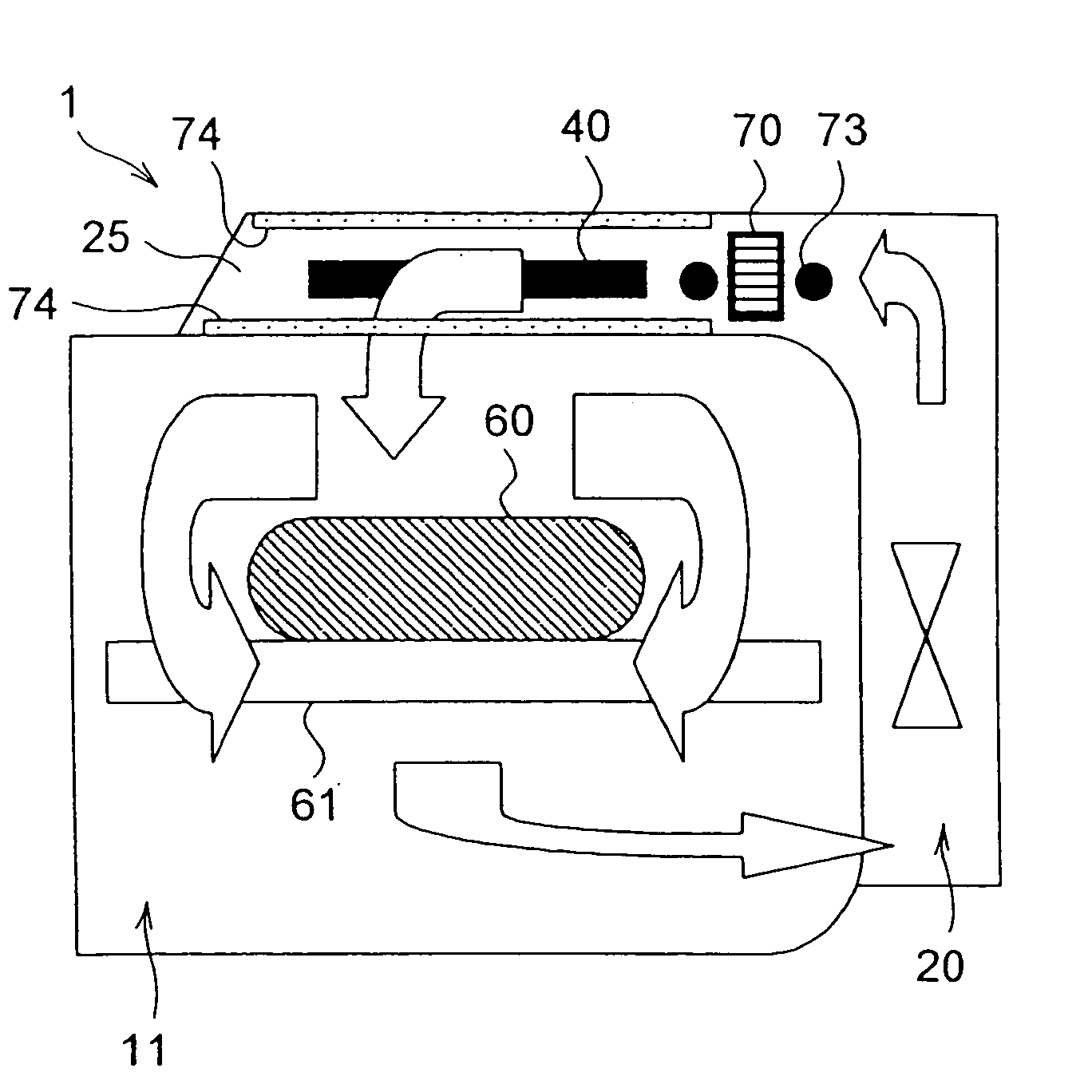
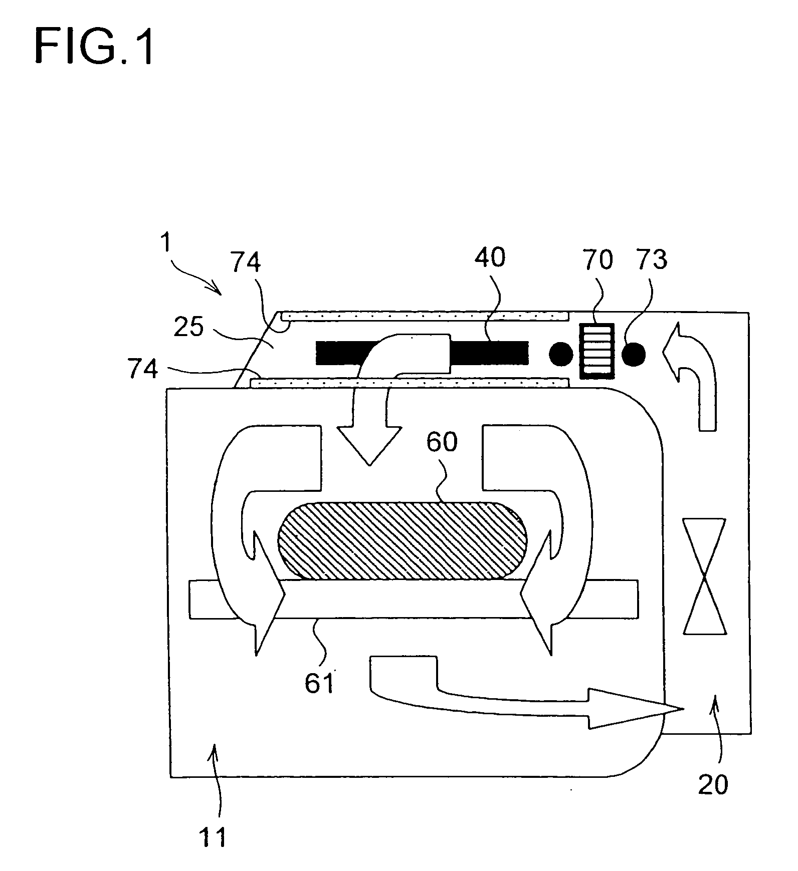
[0071] The catalyst block 70 needs to be used in a temperature range that permits it to function satisfactorily. To achieve this, as a heat source for heating the catalyst block 70, there is provided a catalyst heater. The upper heater 40, which is the main heat source for producing the hot air stream, is shared as the catalyst heater. In the first embodiment, the upper heater 40 is realized with a sheath heater, and part of it is laid near the catalyst block 70 so as to serve as the catalyst heater 73.

[0072] The catalyst block 70 is arranged in such a way that the air stream passes through the inside of the tubular vent ports 72, i.e., in such a way that the length direction of the block as a whole is perpendicular to the air stream. This arrangement is shown in FIG. 4. The catalyst heater 73 is so formed as to face both the upstream and downstream surfaces, with respect to the air stream, of the so arranged catalyst block 70. In other words, the catalyst heater 73 is so shaped as ...

second embodiment

[0087]FIG. 7 shows a The fitting member 80 is fitted not on the upper surface of the ceiling wall 12 but to the ceiling surface of the upper duct 25. In this construction, the catalyst block 70, acted upon by gravitation, spontaneously falls onto the bottom of the frame portion 81 and leaves a gap from the ceiling surface of the upper duct 25. This makes it possible to omit the cut-out pieces 84.

third embodiment

[0088]FIGS. 8 and 9 show a A heater support portion 85 for supporting the bent portion formed at a midpoint of the catalyst heater 73 is formed integrally with one of the anchoring support portions 82 of the fitting member 80. The heater support portion 85 has an engagement cut 86 formed in an edge thereof so that the catalyst heater 73 is fitted into it. Thus, the heater support portion 85 holds the catalyst heater 73 in such a way that the catalyst heater 73 does not make contact with the catalyst block 70.

[0089] As described earlier, the fitting member 80 is made of a metal having a high thermal conductivity. Moreover, the frame portion 81 is kept in surface contact with the top, left-side, and right-side surfaces of the catalyst block 70. Thus, as shown in FIG. 9, the heat generated by the catalyst heater 73 conducts from the heater support portion 85 to the frame portion 81 and then to the catalyst block 70. This permits the catalyst block 70 to be heated efficiently.

[0090]FI...


PUM


Abstract

A cooking oven, wherein air in a cooking chamber is sucked into a blower on the outside of the cooking chamber and fed to an upper duct and a lateral duct, air current led into the upper duct is heated by an upper heater and re-circulated from an upper blowing port to the cooking chamber, a catalyst block heated by a catalyst heating heater is disposed in the upper duct to decompose lamp black and smell substances contained in the air current, catalyst paint is applied onto the inner wall surface of the upper duct to reinforce a performance for decomposing the lamp black and smell substances, both the lateral duct and the upper duct are formed in the same structure, the distributions of heating volumes of the upper heater and the lateral heater in the cross sections of the upper duct and the lateral duct are set so that larger heating volumes are generated on larger air volume sides according to the air volume distributions in the cross sections of the ducts, and the catalyst block is also disposed in the cross sections of the ducts eccentrically to the larger heater heating volume side.

Description

TECHNICAL FIELD [0001] The present invention relates to a cooking oven that cooks foods with heat by application of a hot air stream thereto. BACKGROUND ART [0002] Cooking ovens such as convention ovens and hot-air-impingement ovens that cook foods with heat by forming a circulated current of hot air stream inside a cooking chamber in which foods are placed, are well known and widely used. Published documents such as, to name a few, Japanese Utility Model Published No. H6-23841 and Japanese Patent Applications Laid-Open Nos. H9-145063, Hi1-166737, 2000-329351, and 2001-311518 disclose examples of hot-air-circulation cooking ovens. On the other hand, Japanese Patent Published No. H9-503334 discloses an example of a hot-air-impingement cooking oven. Among these examples, the cooking oven disclosed in Japanese Patent Application Laid-Open No. 2001-311518 has a heater arranged inside a duct through which a air stream is sent to a cooking chamber. [0003] Now, as the basis of the present ...

Claims


Application Information

Patent Timeline
Patent Type & Authority Applications(United States)
IPC IPC(8): F24C15/20F24C15/32
CPCF24C15/325F24C15/2014
Inventor KAMINAKA, IKUYASUNASU, TADASHIIWAMOTO, MASAYUKIANDOH, YUZIHASHIMOTO, TAKASHIIRIE, TOSHIYUKIARITA, TETSUICHI
Owner SHARP KK
Why Eureka
Try Eureka