Gun holster

Inactive Publication Date: 2005-02-24
TACTICAL DESIGN LABS
View PDF90 Cites 26 Cited by
  • Summary
  • Abstract
  • Description
  • Claims
  • Application Information

AI Technical Summary

Benefits of technology

[0020] Another feature of the security holster of the present invention is that the surface of the holster has one or more inlay receiving regions. Each inlay-receiving region is basically a recess in the holster's surface, surrounded by a raised edge. Into each of these recesses, an adhesive backed inlay may be placed. These inlays are the same depth as the recess so that the inlay does not extend above the surface of the holster. Due to the inlay receiving regions, the inner wall of the recess surrounds each edge of each inlay, and no inlay edge is exposed to wear. The result of this is that the recesses protect the inlays from wear, and the inlays do not tend to peel up at the edges. The purpose of the inlays is to allow the holster to receive a decorative surface to match the requirements of any particular gun user. For instance, one particular police department may require a certain style or finish on the accessories that the officers carry. In this way, a plastic holster can be covered with a decorative surface pattern, such as basket weave, to match the other accessories being carrie

Problems solved by technology

However, after the handgun is withdrawn, the situation may dictate other options or needs, requiring the officer to re-holster the handgun just as quickly.
Current holsters do not meet this demand, without some continued manipulation of security straps, before the officer knows or has confidence that the weapon is secure.
The problem results when a suspect becomes an assailant, and attacks the officer and tries to gain access to his weapon.
In the event of an attack, a holster is likely to be bumped, jostled, pried, and pressured with forces exerted on nearly any part of the holster.
Some holsters have release mechanisms that may be accidentally engaged during such an assault, releasing the weapon from the effective grip of the holster.
However, they all suffer a number of drawb

Method used


Image

  • Gun holster
  • Gun holster
  • Gun holster

Examples


Embodiment Construction

[0040] While the invention is susceptible to various modifications and alternative constructions, certain illustrated embodiments thereof have been shown in the drawings and will be described below in detail. It should be understood, however, that there is no intention to limit the invention to the specific form disclosed, but, on the contrary, the invention is to cover all modifications, alternative constructions, and equivalents falling within the spirit and scope of the invention as defined in the claims.

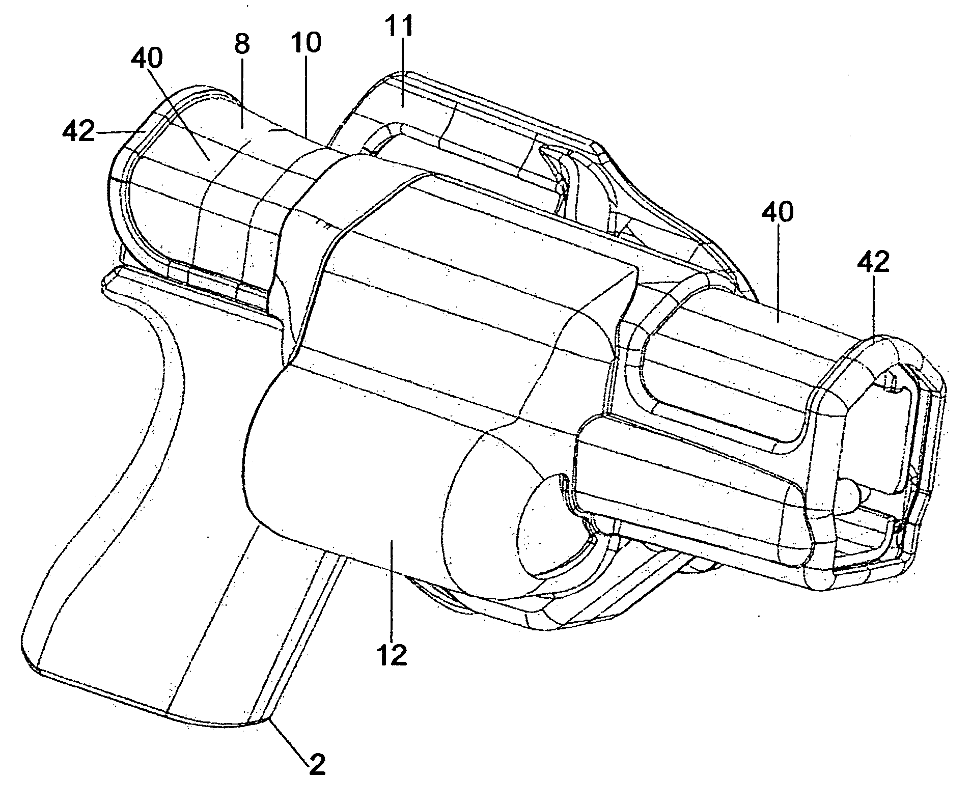
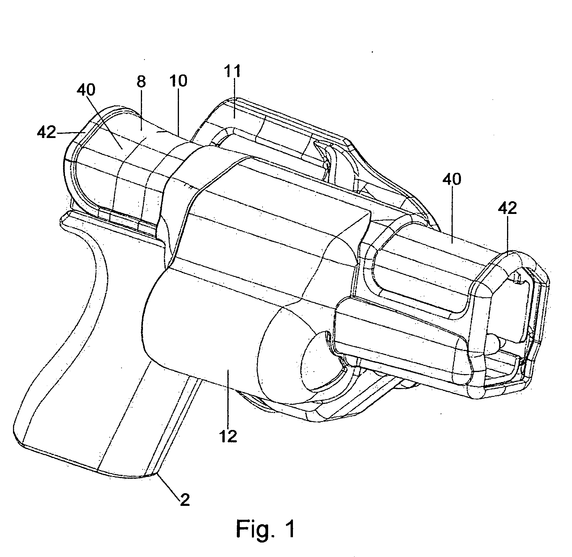
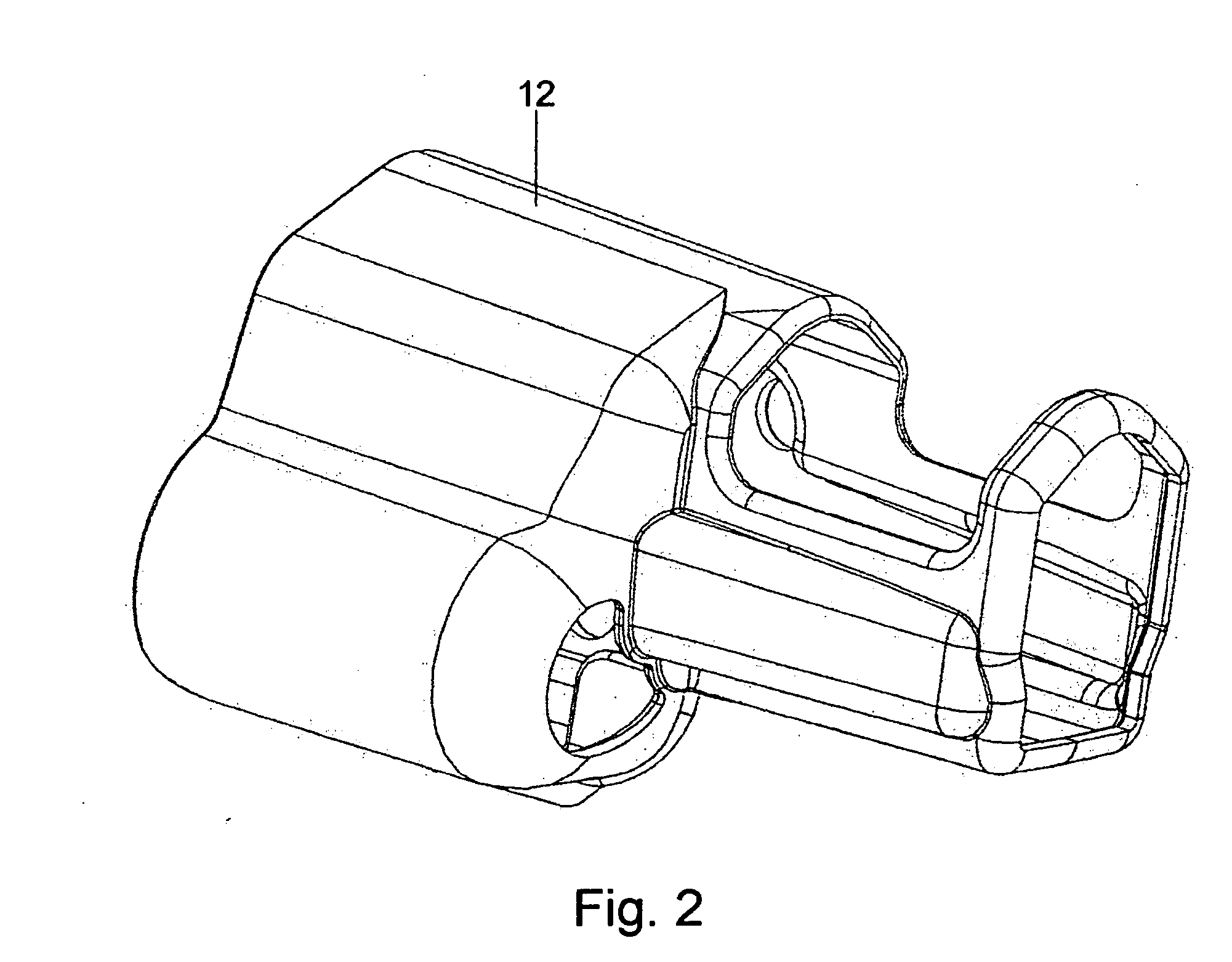
[0041] The present invention is a security holster for use with a handgun that allows rapid insertion of the handgun and equally rapid withdrawal of the handgun. The security holster also provides a secure locking mechanism that secures the handgun in the holster until the user releases it.

[0042] Several preferred embodiments and features of the security holster are shown in FIGS. 1-14. The security holster shown in FIG. I shows a perspective view of the general configuration o...


PUM


Abstract

A security holster for handguns which utilizes a U-shaped rod as part of the locking and releasing mechanism. The user presses a handgun against a portion of the U-shaped rod, which pushed the U-shaped rod forward, and causes the locking tab to seat against the ejection port or another feature of the handgun.

Description

PRIORITY [0001] This application claims priority from a provisional patent application filed on Jun. 25, 2003 with application Ser. No. 60 / 482,824 entitled “Security Holster”.DESCRIPTION BACKGROUND OF THE INVENTION [0002] 1. Field of the Invention [0003] The present invention generally relates to handgun holsters, and more particularly relates to holsters, which provide security against unauthorized withdrawal of a handgun. [0004] 2. Background Information [0005] Police, security officers, and military personnel in a number of situations must be ready to withdraw and use a handgun in the line of duty at a moment's notice. In an emergency situation, withdrawing the handgun must be done in a completely natural and unobstructed manner so that it can be withdrawn as quickly as possible. The officer's life may depend on the speed with which he can withdraw the handgun. However, after the handgun is withdrawn, the situation may dictate other options or needs, requiring the officer to re-h...

Claims


Application Information

Patent Timeline
IPC IPC(8): F41C33/02
CPCF41C33/0209F41C33/0263F41C33/0254F41C33/0236Y10S224/912
Inventor LOWE, MICHAEL V.SENN, ANTHONY J.YATES, ERIC
Owner TACTICAL DESIGN LABS
Why Eureka
Try Eureka