A transparent transaction device

a transaction device and transparent technology, applied in the field of transactions, can solve the problems of inability the ability to save the device, and the user's loss of the ability to reuse the device, etc., and achieve the effect of efficient transaction

Inactive Publication Date: 2005-02-24
LIBERTY PEAK VENTURES LLC
View PDF99 Cites 134 Cited by
  • Summary
  • Abstract
  • Description
  • Claims
  • Application Information

AI Technical Summary

Benefits of technology

[0013] It is, therefore, an object of the present invention to provide a transaction device that is clear or otherwise transparent, thereby giving the transaction device a distinctive appearance. Moreover, it is an object of the present invention to provide a transparent transaction device having means for sending information to a machine or card reader in a contactless operating environment.
[0014] In addition, it is an object of the present invention to provide a transparent transaction device having one or more RF-based chips therein and corresponding antennae for sending information stored on the chips to a receiver or reader and receiving information from the same. The RF-based chips and antennae are incorporated into the clear transaction device to further give the transaction device a distinctive appearance, since the RF-based chip and the antenna are viewable through the transaction device body.
[0015] Further, it is an object of the present invention to provide a contactless transparent transaction device that allows consumers and merchants to more effectively, more quickly, and more efficiently conduct transactions. The present invention allows a consumer to maintain a substantial amount of control over the transaction device during transaction processing. In that regard, the present invention allows for a consumer to conduct a transaction with minimal need for, or without the need for, a representative of the merchant to be present.
[0016] In one embodiment, the present invention relates to a process for producing a transparent or translucent transaction device having any one or more features, such as a holographic foil, integrated circuit chip, silver magnetic stripe with text on the magnetic stripe, opacity gradient, perforations included in the transparent device body for forming an outline of a shape, an optically recognizable ink or film contained within the construction of the device, a translucent signature field such that the signature on back of the device is visible from the front of the device and an “active thru” date on the front of the device. The transparent transaction device is optically recognizable during, for example, manufacture, due to an invisible or transparent infrared ink or film which is distributed over the device's surface, thereby allowing the device to block (absorb, refract, diffuse and / or reflect) infrared light and transmit all other light. Particularly, when the transaction device is manufactured, the light beam from a IRED used for counting devices during manufacture is blocked by the infrared ink or film, thereby deactivating the phototransistor permitting the manufacturing equipment to detect transaction device presence. More particularly, during the manufacturer of transaction devices, the optically recognizable film allows an IRED light beam from a personalization device, inspection unit or counter device to count the number of transaction devices produced in an assembly line.

Problems solved by technology

These payment means, however, were often difficult or impossible to replace if lost or stolen.
This is typically true, since these means of payment were disposable in that they were typically single-use devices, meaning that once the devices were used, the ability to reuse the devices was instantly lost to the user.
However, although transaction cards are typically configured for re-use, they, like the traditional means of payment discussed above, are often misplaced or lost by the user.
The security provided by this attachment method is limited, however, since the transaction device may still need to be handed over to a merchant to complete a transaction.

Method used


Image

  • A transparent transaction device
  • A transparent transaction device
  • A transparent transaction device

Examples


Embodiment Construction

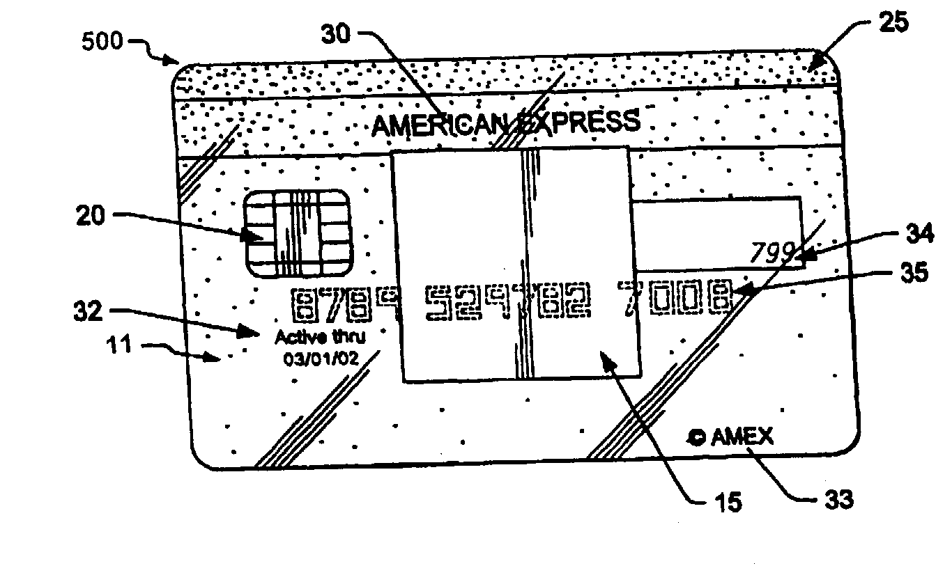
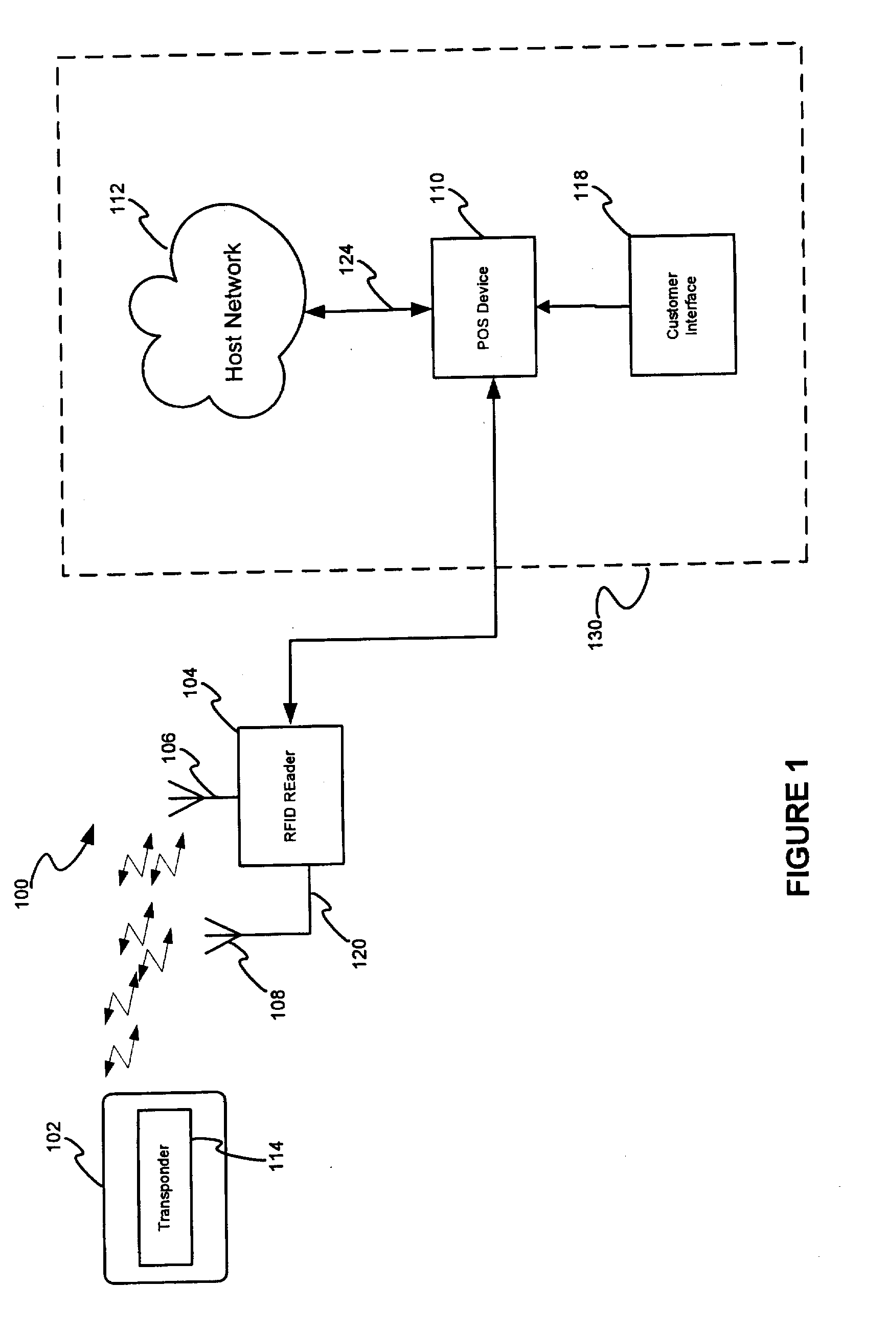
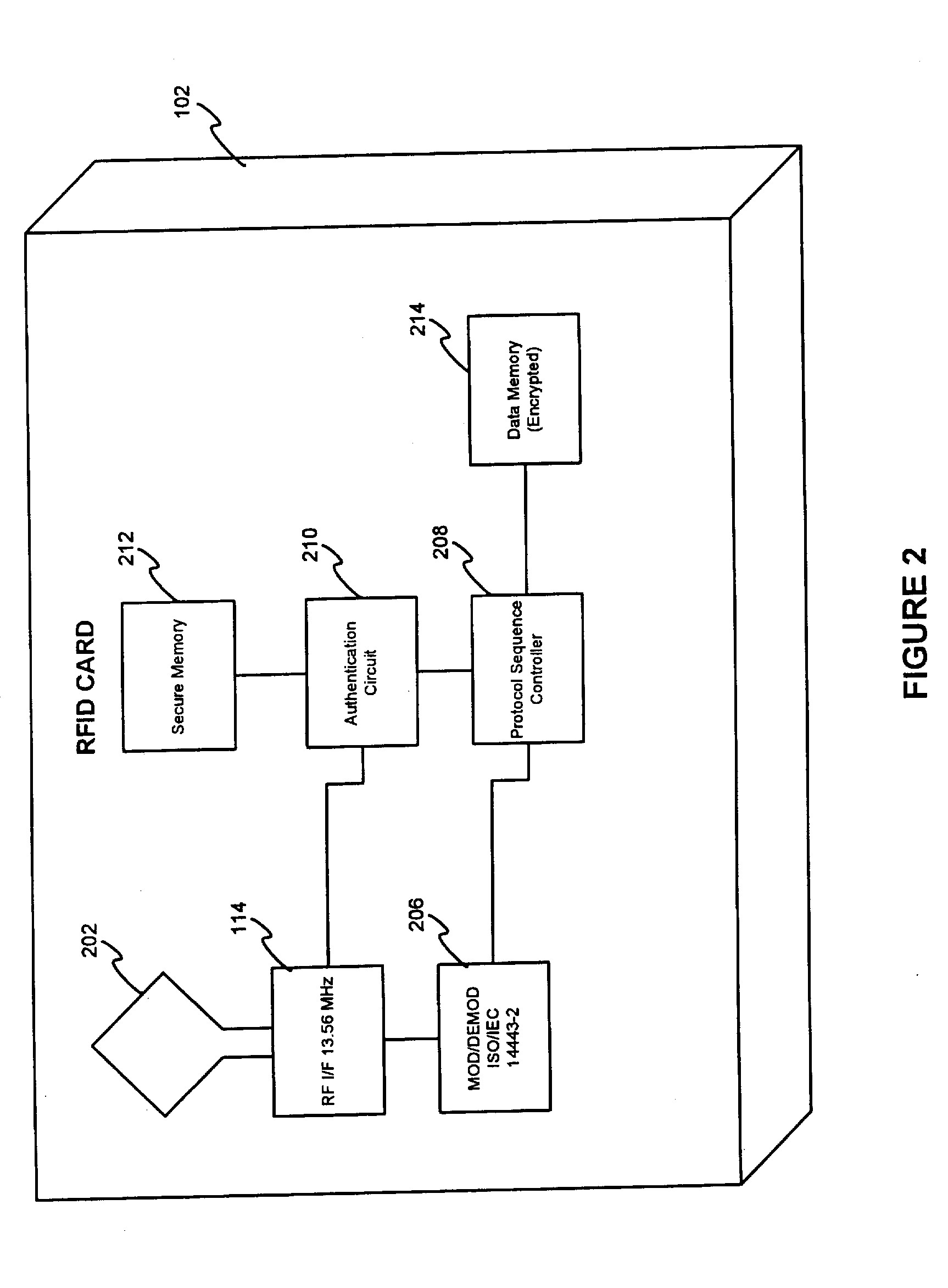
[0039] The present invention relates to contactless transparent transaction devices and methods of making and using the same. Specifically, the present invention relates to a contactless, transparent transaction device, having a plurality of layers that is transparent or otherwise clear so that the transaction device is see through. The transaction device may include means for conducting a transaction in a contactless environment. For example, the transaction device may include a transponder system, which may include a RF-based chip and antenna embedded therein. The contactless transparent transaction device can be utilized to efficiently conduct cashless transactions at merchants, for example, a merchant POS, by permitting the accountholder to maintain possession of the device throughout the transaction. Instead, the device user account information necessary to complete the transaction is retrieved from the device using contactless means. In addition, the transaction device may fur...


PUM


Abstract

The present invention relates to a process for producing an transparent or translucent transaction device having multiple features, such as a holographic foil, integrated circuit chip, RFID circuitry, silver magnetic stripe with text on the magnetic stripe, opacity gradient, an invisible optically recognizable compound, a translucent signature field such that the RFID circuitry and signature on back of the device is visible through the device body. The invisible optically recognizable compound is an infrared ink and / or film, which can be detected by a sensor found in an ATM or device manufacturing assembly line.

Description

CROSS REFERENCE TO RELATED APPLICATIONS [0001] This invention is a continuation in part of and claims priority to U.S. patent application Ser. No. 10 / 192,488, entitled “SYSTEM AND METHOD FOR PAYMENT USING RADIO FREQUENCY IDENTIFICATION IN CONTACT AND CONTACTLESS TRANSACTIONS,” filed on Jul. 9, 2002 (which itself claims priority to U.S. Provisional Patent Application No. 60 / 304,216, filed Jul. 10, 2001). This invention is also a continuation in part of U.S. patent application Ser. No. 10 / 394,914, entitled “TRANSACTION CARD,” filed Mar. 21, 2003 (which itself claims priority to U.S. Provisional Patent Application No. 60 / 153,112, filed Sep. 7, 1999, U.S. Provisional Patent Application No. 60 / 160,519, filed Oct. 20, 1999, U.S. Provisional Application No. 60 / 167,405, filed Nov. 24, 1999, and to U.S. Provisional Patent Application No. 60 / 171,689, filed Dec. 21, 1999) and continuation in part U.S. patent application Ser. No. 10 / 611,563, entitled “TRANSPARENT TRANSACTION CARD,” and of conti...

Claims


Application Information

Patent Timeline
Patent Type & Authority Applications(United States)
IPC IPC(8): G06K7/00G06K19/02G06K19/07G06K19/077G06K19/08G06K19/16G06Q20/00G07C9/00G07F7/08H04L9/32
CPCG06K7/0008H04L9/32G06K19/0723G06K19/077G06K19/08G06K19/16G06Q20/00G06Q20/04G06Q20/14G06Q20/327G06Q20/3278G07C9/00111G07C9/00119G07F7/086G06K19/02G07C9/28G07C9/29H04L9/3231H04L9/3273H04L2209/56H04L2209/805Y04S40/20
Inventor BEENAU, BLAYN W.BONALLE, DAVID S.EYK, BECKY VANDERISENBERG, SUSAN E.MALNATI, LEIGHMUELLER, SUENORCROSS, ZARITAPEART, LEE J.SAUNDERS, PETER D.SKILLING-BELMOND, LISAWEBB, LIDAWILLIAMSON, JOHN R.
Owner LIBERTY PEAK VENTURES LLC
Why Eureka
Try Eureka