Vehicle lean and alignment control system

a control system and vehicle technology, applied in the field of vehicles, can solve the problems that the counter steering mechanism is generally restricted to operation, and achieve the effects of increasing the adhesion patch, speeding up the stopping speed, and increasing the speed around corners

Inactive Publication Date: 2005-02-24
MELCHER THOMAS WESLEY
View PDF3 Cites 37 Cited by
  • Summary
  • Abstract
  • Description
  • Claims
  • Application Information

AI Technical Summary

Benefits of technology

[0007] The present invention relates to a vehicle that includes many of the advantages of a motorcycle on a vehicle having three or more wheels. With the frame and suspensions of the present invention, the same advantages of leaning the wheels and the frame of the vehicle supported on the frame are provided. With each additional wheel over two, an additional adhesion point is provided. Thus, a vehicle with four wheels will have twice as many adhesion points as a standard motorcycle. As such, the vehicle will enable faster stopping. Also, the vehicle can automatically lower the frame and provide a lower center of gravity of the vehicle during deceleration. One way of carrying this out is to automatically cause the rear suspension to mirror the front suspension during braking. Furthermore, it is contemplated that approximately a thirty percent increase in speed around corners may be achieved with the present invention. This is due, in part, to the increased adhesion patch at each of the adhesion points when the wheels are leaned during turning. Still further, with the frame leaning into turns, the centrifugal and gravitational forces are more evenly distributed among the adhesion points. The vehicle can include additional advantages of automatically leaning the frame and wheels and aligning the rear wheels. Aligning the rear wheels reduces drag that typically occurs during turns, and thus improves gas mileage or efficiency in general.
[0008] Another advantage provided by the frame and suspension of the present invention is that they include shock absorption by way of shock absorbers and an electro-mechanical tracking mechanism. The term “shock absorbers” as used throughout this disclosure can include a spring coiled over a shock absorption device, a torsion bar, or an air shock for example. In any case, it is to be understood that “shock absorber” as used herein refers to a mechanism having support characteristics capable of supporting the chassis and body weight of a vehicle and having shock absorbing characteristics. The shock absorption of the frame and suspension can be in addition to shock absorbers on a vehicle body, such as on a motorcycle body. That is, the motorcycle body with its front and rear shocks can be supported on the frame and suspension of the present invention. As can be appreciated this offers redundancy and provides an exceedingly smooth ride. The stiffness of the various shock absorbers and tracking mechanism can be varied to absorb a variety of shock and vibrations.
[0009] The shock absorbers of the frame and suspension system of the present invention are mounted as close to a central longitudinal axis as possible. This location together with the structural relationship of the shock absorbers to the frame and suspension provides the advantage of increased mechanical advantage for forces applied to the wheels, the frame, vehicle body, and the driver / rider(s) with increased lean.
[0010] The change in position of the shock absorber(s) relative to the lower arm helps reduce the transfer of force to the other side of the frame. Furthermore, the present suspension includes an arm assembly for each wheel that it supports. Each arm assembly can be deflected independently so that the load is minimally transferred to the other side of the frame.

Problems solved by technology

These counter steering mechanisms are generally restricted to operation at low speeds.

Method used


Image

  • Vehicle lean and alignment control system
  • Vehicle lean and alignment control system
  • Vehicle lean and alignment control system

Examples


Embodiment Construction

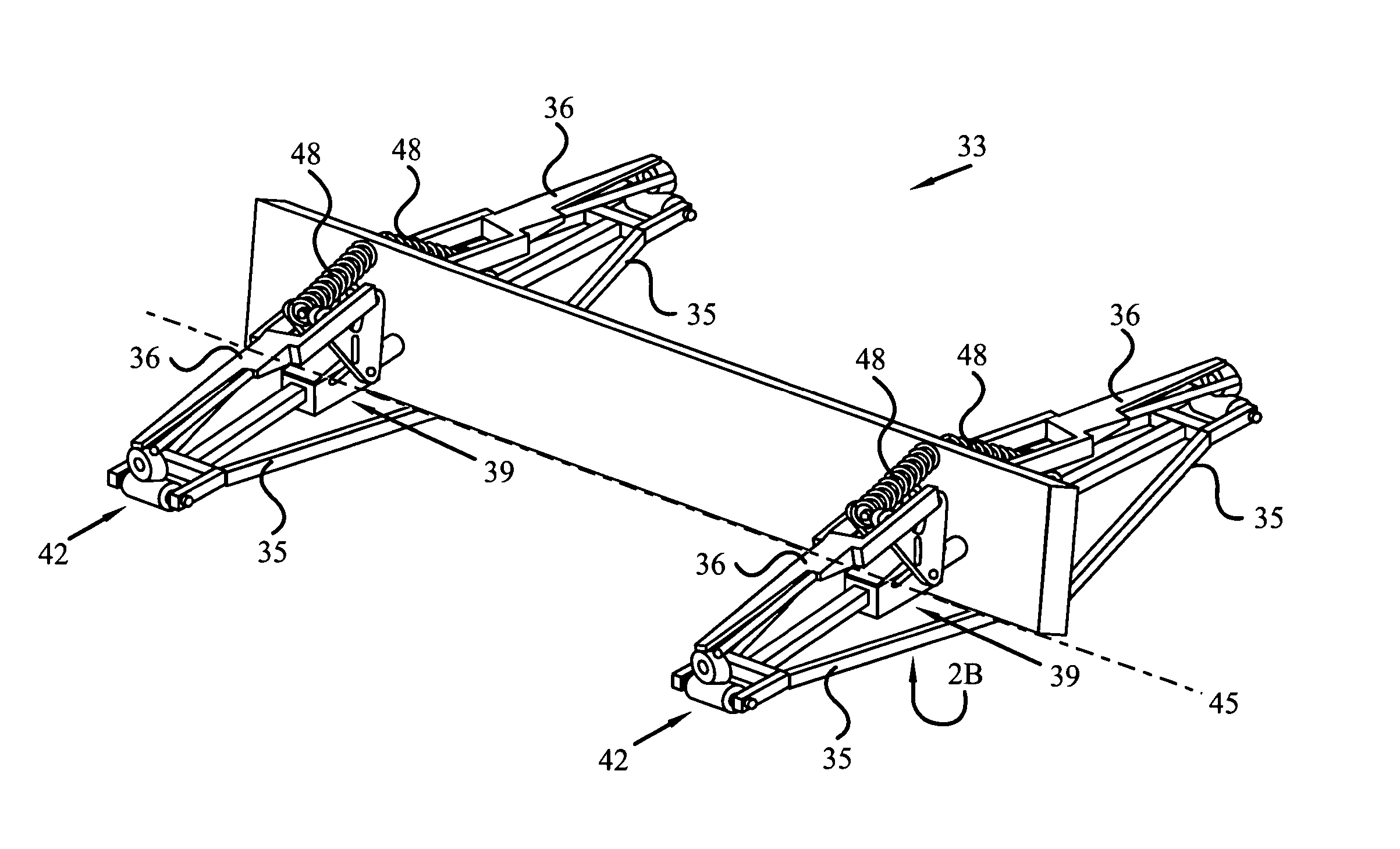
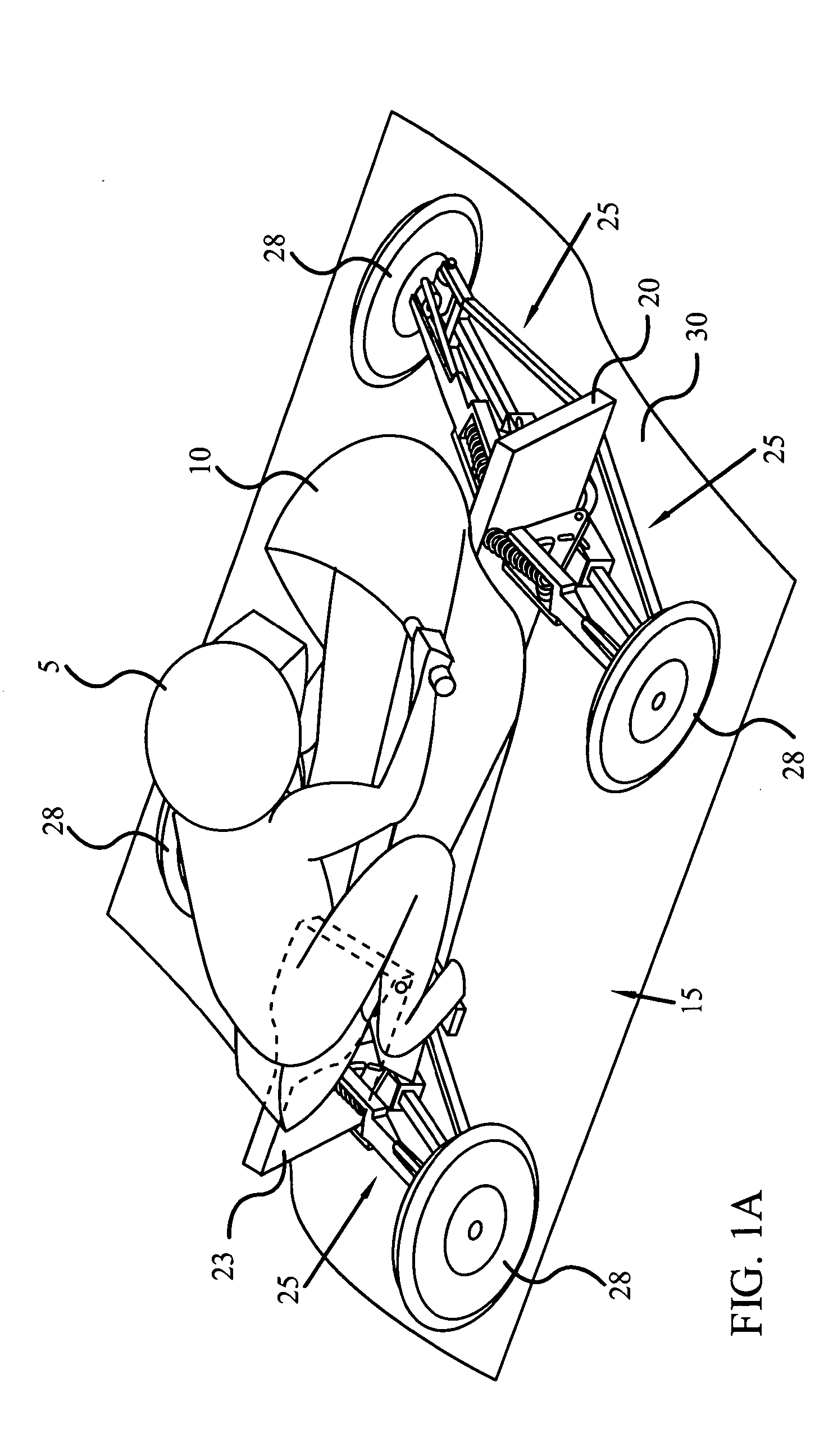
[0040] As discussed above, embodiments of the present invention relate to a vehicle, and a frame and a suspension system for the vehicle.

[0041] As shown in FIG. 1A, a driver 5 is seated on a vehicle 10 that is supported on a frame and suspension system 15 in accordance with the present invention. In the example of FIG. 1, the frame and suspension system includes a front frame 20 and a swing arm frame 23. Each of frames 20 and 23 has separate suspensions in the form of arm assemblies 25. Each arm assembly 25 is independently and pivotally connected to the frames 20, 23. The arm assemblies 25 support wheels 28 at outboard ends. The wheels 28, of course, support the frame and suspension system 15 and the vehicle 10 on a driving surface 30.

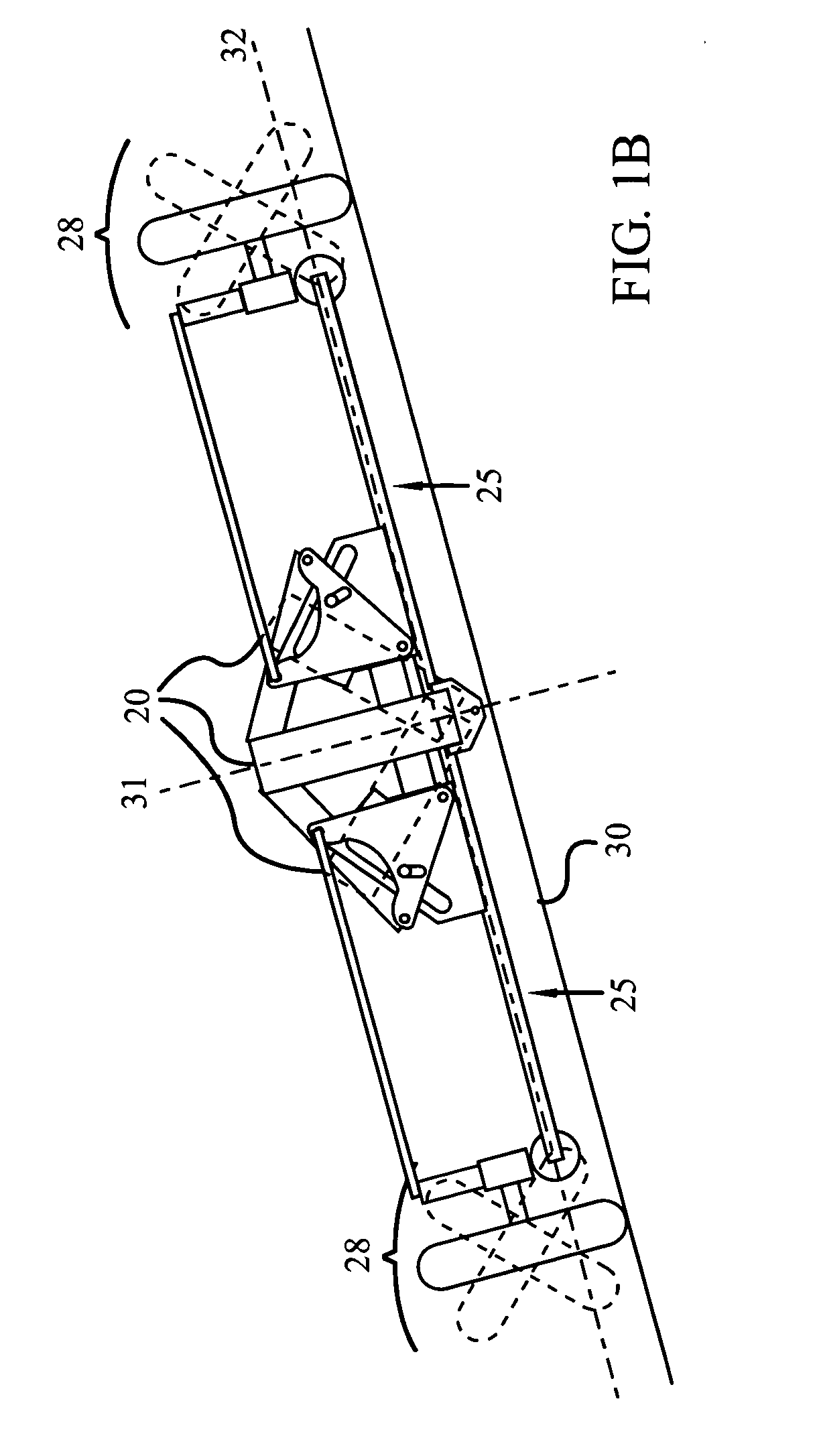
[0042] As can be appreciated from the diagrammatic end view of FIG. 1B, the arm assemblies 25 permit the frames 20, 23 to lean through a range of angles relative to a plane 31 that is upright and substantially perpendicular to a plane 32 defined by ...


PUM


Abstract

A frame and suspension for a vehicle provides automatic lean and alignment. The lean is determined by force sensors, the speed and / or the angle of turn and is provided by actuators in the suspension in accordance with a predetermined protocol in an electronic control unit (ECU). The protocol also provides shock absorption by rapidly tracking a contour of a surface on which the vehicle rides. The suspension is provided by a plurality of arm assemblies each including a lower arm, an upper control arm, and an actuator motively connected to the lower arm and to the upper control arm. The arm assemblies are pivotally connected to the frame on a common axis. The arm assemblies generally form parallelograms and are actuated in concert to remain generally parallel to each other through a range of angles to adjust the lean of the vehicle. The arm assemblies are also actuated independently of each other to accommodate variations in the contour. In one aspect, an actuator controlled by an ECU can be replaced by a mechanical actuator that can be activated manually such as by a driver's own leaning weight.

Description

[0001] This application is a continuation-in-part of U.S. patent application Ser. No. 10 / 428,274 by Thomas Wesley Melcher, filed May 2, 2003.BACKGROUND OF THE INVENTION [0002] 1. Technical Field [0003] This invention generally relates to vehicles that are capable of being leaned and that have rear steering capabilities, and more specifically to a frame and suspension system that facilitates leaning and rear steering on a vehicle having more than two wheels. [0004] 2. Background Art [0005] Vehicles capable of leaning include motorcycles. Of course, standard configuration motorcycles have only two wheels so that leaning the vehicle happens naturally. The benefits of leaning include that leaning facilitates turning. Leaning the motorcycle in a direction while the motorcycle is moving forward actually pulls the front steering in the same direction. Another benefit of leaning the motorcycle is that the wheels are also leaned and better support the forces applied to the wheel and tire. At...

Claims


Application Information

Patent Timeline
Patent Type & Authority Applications(United States)
IPC IPC(8): B60G3/18B60G7/00B60G17/015B60G17/016B60G17/0165B60G21/00B62D9/02B62K5/00
CPCB60G7/006B60G17/0162B60G17/0165B60G21/007B60G2200/144B60G2200/46B60G2202/413B60G2202/42B60G2202/442B60G2204/13B60G2204/143B60G2204/20B60G2204/421B60G2204/4232B60G2300/45B62D9/02B62K5/10B62K2005/001
Inventor MELCHER, THOMAS
Owner MELCHER THOMAS WESLEY
Why Eureka
Try Eureka