Smart and active antenna array for portable and mobile television reception

a technology of active antenna array and portable and mobile tv, which is applied in the direction of multi-antenna systems, color television details, television systems, etc., can solve the problems of limiting the flexibility of viewers to move the set about, affecting the quality of picture, and affecting the reception quality of urban and suburban locations with typical indoor antennas. achieve the effect of enhancing at least one of the quality and reliability of tv reception, and minimizing noise figures and maximum signal level transfer

Inactive Publication Date: 2005-02-24
TV TRANSMISSION ANTENNA GRP
View PDF7 Cites 14 Cited by
  • Summary
  • Abstract
  • Description
  • Claims
  • Application Information

AI Technical Summary

Benefits of technology

An apparatus according to a further aspect of the invention comprises a television display having a diagonal of at least 13 inches, and electronics for providing a display of a received television signal. The electronics includes a channel tuner. A casing surrounds at least a portion of the apparatus including a portion of the display and the electronics. The apparatus further includes at least first and second electronically integrated antenna-WLNA elements. Each of the integrated antenna-WLNA elements includes an output port, and provides substantially minimum noise figure and maximum signal level transfer from the antenna to the output port. Each of the antenna-WLNA elements also includes a bias voltage input port. The integrated antenna-WLNA elements are arranged in an array in which the elements are spaced apart by at least six inches, wit

Problems solved by technology

This tethered arrangement is unsightly and limits the flexibility of the viewer to move the set about.
Some residential communities do not permit installation of rooftop antennas, thereby requiring the use of indoor antennas.
For analog television (ATV) received with typical indoor antennas such as loops, monopoles and “rabbit-ears” the picture quality is often very poor, especially if the position of the indoor antenna is n

Method used


Image

  • Smart and active antenna array for portable and mobile television reception
  • Smart and active antenna array for portable and mobile television reception
  • Smart and active antenna array for portable and mobile television reception

Examples


Embodiment Construction

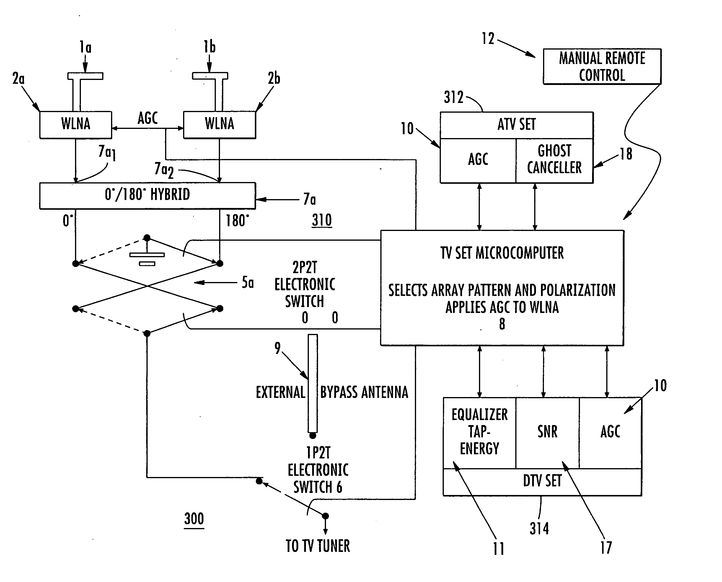
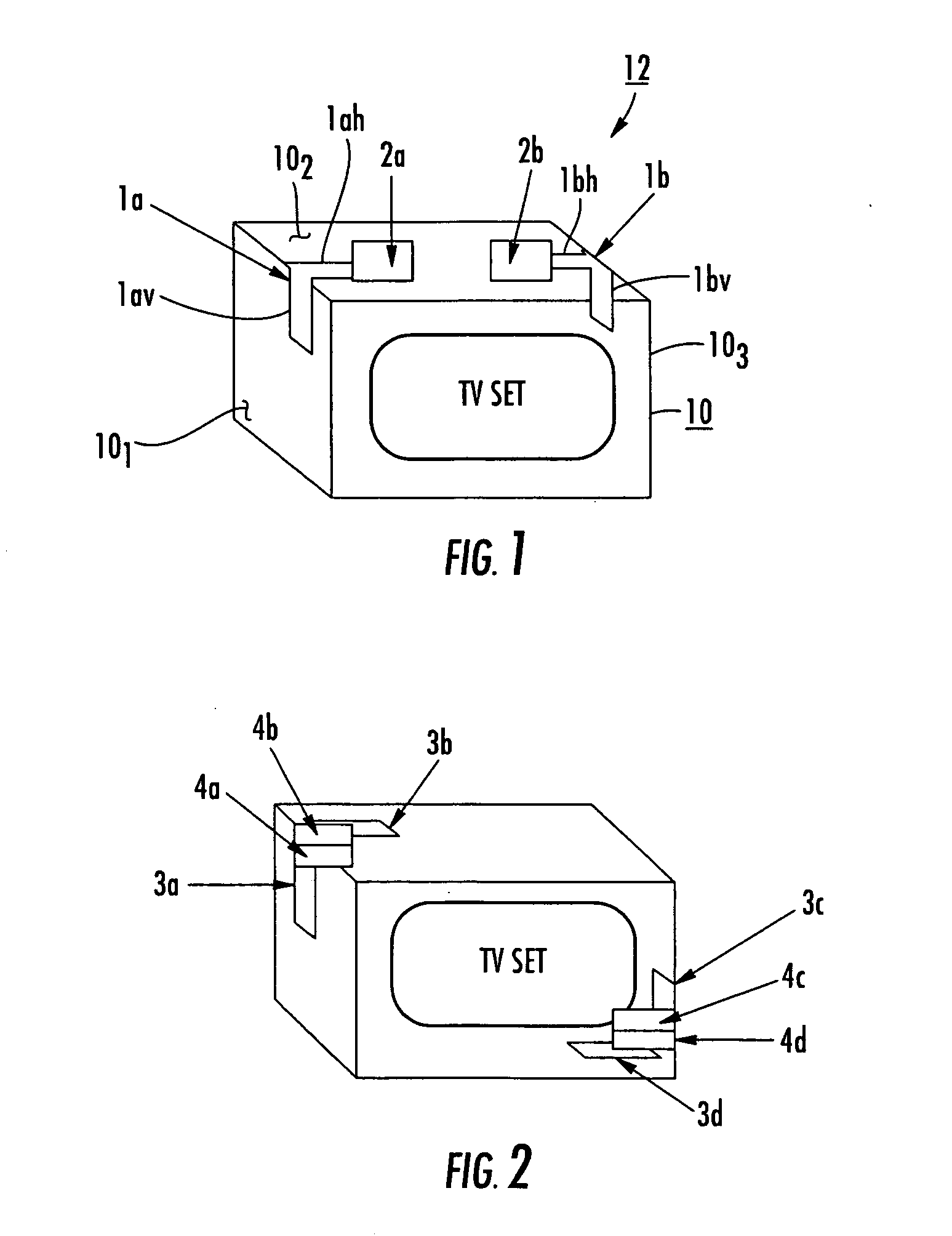
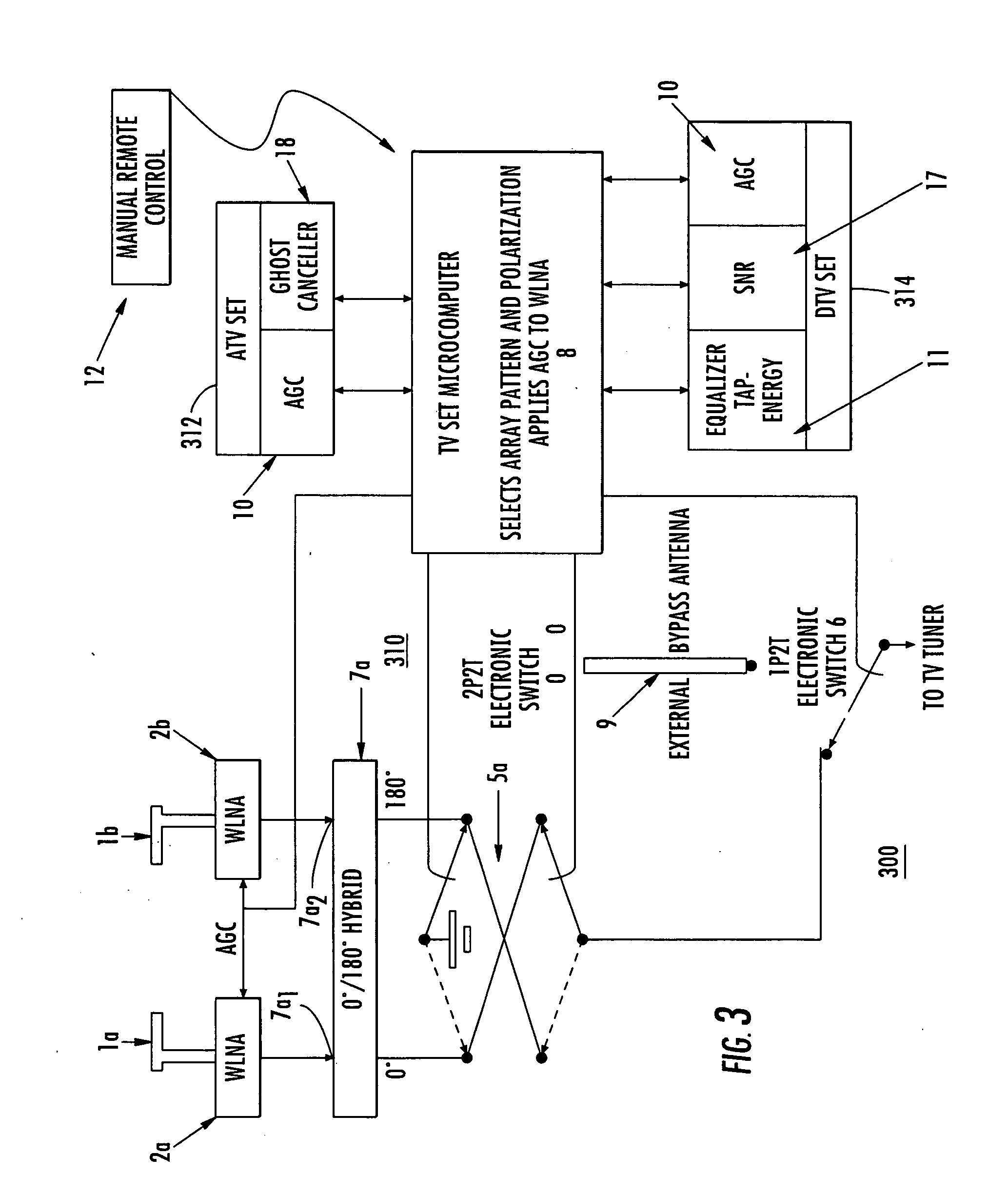
The inventor herein has determined that designs shown in the abovecited Verma, Woodward, and Torres patents fail to focus on two important system design criteria. The first such important criterion is that of matching, over the television bandwidth, the antenna's input impedance to the conjugate input impedance of the television receiver's front-end at the front-end's point of minimum noise FIGURE. The second such important criterion is that of providing an antenna array with controlled polarization diversity and space diversity reception by automatically switching individual radiators within the array automatically or manually to attain optimum reception regardless of the physical location of the TV set. For optimum reception, the concealed array must make use of very small, active, broadband antennas designed to minimize the noise FIGURE of the receiver at all TV channels, rather than be made of large loops tuned to maximize the voltage of the tuned loop at the antenna's terminal...


PUM


Abstract

A television receiving apparatus includes a tuner having an input port for image-representative signals, an input port for an external antenna, and an internal or associated external indoor antenna array including at least two electronically integrated antenna-WLNA elements. A processor includes a plurality of RF switches and at least one hybrid, for selectively generating a plurality of signals including sums and differences of signals from said elements. The sums and differences are compared with each other and with the external antenna signal to select the best signal, and that selected best signal is coupled to the input port of the tuner.

Description

FIELD OF THE INVENTION This invention relates to arrays of antenna elements for reception of television signals, and more particularly to such antennas suitable for use inside the television receiver or outside, but associated with, the receiver. BACKGROUND OF THE INVENTION Conventional television reception requires an outdoor rooftop or an indoor set-top antenna. This tethered arrangement is unsightly and limits the flexibility of the viewer to move the set about. Some residential communities do not permit installation of rooftop antennas, thereby requiring the use of indoor antennas. For analog television (ATV) received with typical indoor antennas such as loops, monopoles and “rabbit-ears” the picture quality is often very poor, especially if the position of the indoor antenna is not adjusted for the particular channel being watched. For digital television (DTV), which is expected to be the future of wireless television worldwide, reception in urban and suburban locations with ...

Claims


Application Information

Patent Timeline
IPC IPC(8): H04B7/10H04N5/52
CPCH04B7/10H04N21/42638H04N5/52
Inventor BENDOV, ODED
Owner TV TRANSMISSION ANTENNA GRP
Why Eureka
Try Eureka