Active multiple-color imaging polarimetry

a polarimetry and multiple-color technology, applied in the field of remote sensing, can solve problems such as trouble, image mis-registration, and mis-registration to some degree, and achieve the effect of avoiding mis-registration among images

Active Publication Date: 2005-02-24
HARRIS CORP
View PDF10 Cites 18 Cited by
  • Summary
  • Abstract
  • Description
  • Claims
  • Application Information

AI Technical Summary

Benefits of technology

[0008] Systems and processes consistent with the principles of the invention may extract different polarization information from a single detection signal, thereby avoiding mis-registration among images.

Problems solved by technology

In such a scheme, however, image mis-registration, where corresponding pixels in different detectors do not spatially correspond to the same location on the target, becomes troublesome.
These schemes, however, also suffer the mis-registration problem to some degree.

Method used


Image

  • Active multiple-color imaging polarimetry
  • Active multiple-color imaging polarimetry
  • Active multiple-color imaging polarimetry

Examples


Embodiment Construction

[0017] The following detailed description of the invention refers to the accompanying drawings. The same reference numbers may be used in different drawings to identify the same or similar elements. Also, the following detailed description does not limit the invention. Instead, the scope of the invention is defined by the appended claims and equivalents.

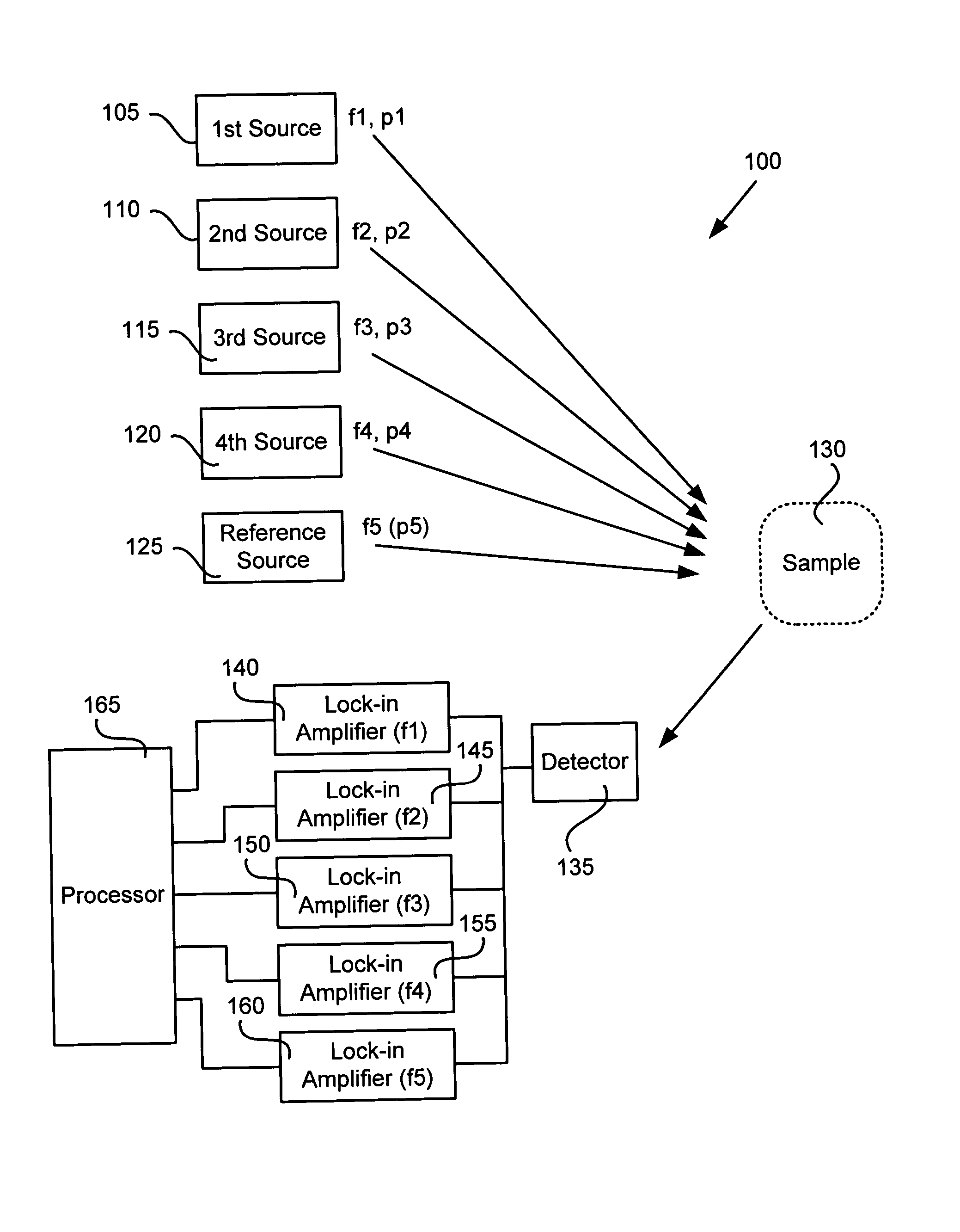
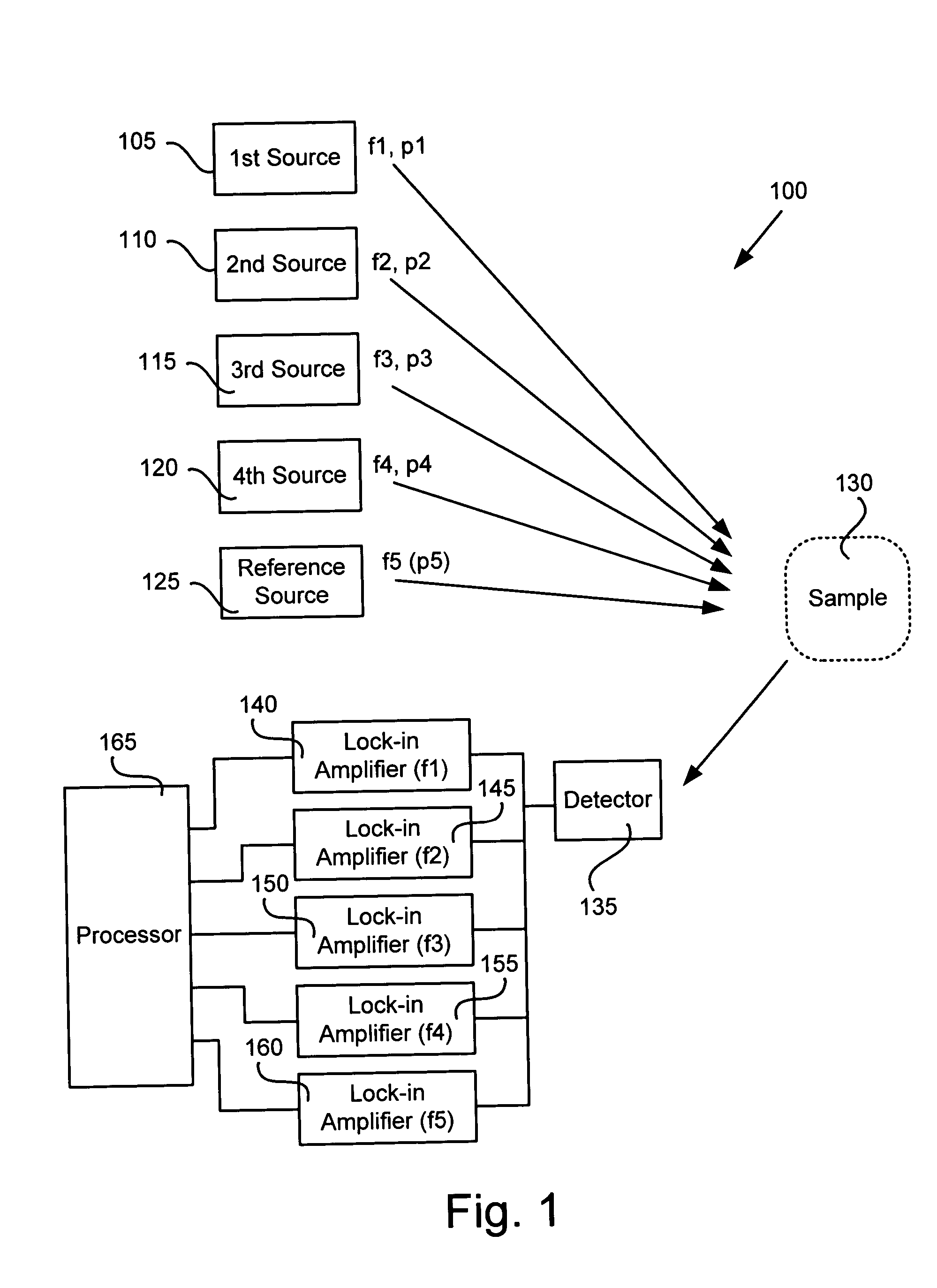
[0018] As described herein, in one implementation consistent with the principles of the invention, a remote sensing system may modulate radiation at different frequencies and polarize the radiation with different polarizations before interaction with a sample of interest. A number of lock-in amplifiers may be used to process radiation detected from the sample to obtain information at the different polarizations from the sample.

EXEMPLARY SYSTEM

[0019]FIG. 1 is a schematic diagram of an exemplary active remote sensing system 100 according to an implementation consistent with the principles of the invention. System 100 may include fir...


PUM

PropertyMeasurementUnit
modulation frequenciesaaaaaaaaaa
frequencyaaaaaaaaaa
optical radiationaaaaaaaaaa

Abstract

Remotely sensing a target may include generating a first beam of optical radiation that is modulated at a first frequency and polarized at a first polarization. A second beam of optical radiation that is modulated at a second frequency and polarized at a second polarization may also be generated. The first and second beams of optical radiation may be transmitted to the target. Radiation at the first polarization and radiation at the second polarization may be detected from the target using a phase sensitive technique and the first and second frequencies.

Description

BACKGROUND OF THE INVENTION [0001] 1. Field of the Invention [0002] This invention relates to remote sensing and, more particularly, to active remote sensing and specifically active polarimetery. [0003] 2. Description of Related Art [0004] Active remote sensing may be conceptualized as viewing radiation reflected and / or emitted from a certain location. Active remote sensing typically utilizes one or more sources of radiation (e.g., infrared, visible, or ultraviolet light) to illuminate a target area while measuring the reflected, scattered and / or emitted radiation at one or more detectors. Where the detector(s) in a sensor produce or construct a two-dimensional image of the target that includes a number of pixels, such a sensor is typically referred to as an “imaging” sensor. Such remote sensing may be performed from a moving platform or from a stationary location, each of which may be spatially remote from the target area. [0005] One type of remote sensor, such as a spectrometer, m...

Claims


Application Information

Patent Timeline
Patent Type & Authority Applications(United States)
IPC IPC(8): G01J3/447G01J4/04G01N21/21
CPCG01J3/447G01N21/21G01N2201/0691G01N2021/1793G01N2021/1757
Inventor DOBBS, MICHAEL E.PRUITT, JEFF D.GYPSON, MATTHEW L.NEFF, BENJAMIN R.
Owner HARRIS CORP
Why Eureka
Try Eureka