
Safety interlock apparatus and method

a safety interlock and apparatus technology, applied in the direction of switches, contact mechanisms, relays, etc., can solve the problems of requiring a relatively large safety interlock switch, and affecting the use of ultra-portable projectors, so as to prevent users from receiving electrical shocks. , the effect of compact and inexpensive design

Inactive Publication Date: 2005-02-24
SEIKO EPSON CORP
View PDF18 Cites 3 Cited by
  • Summary
  • Abstract
  • Description
  • Claims
  • Application Information

AI Technical Summary

Benefits of technology

This patent describes a lamp apparatus for portable and ultra-portable image projectors. It includes a safety interlock apparatus for an electrical device that prevents users from receiving electrical shocks. The apparatus includes a DC power supply, a ballast power supply, and a lamp all housed within a frame. A low voltage electrical connection is present between the DC power supply and the ballast control circuit, and a high voltage electrical connection is present between the lamp and the ballast power circuit. A switch is positioned on the low voltage electrical connection, and a panel is fixable to the frame to close the cavity within the frame, and selectively movable to expose the lamp for removal. The panel has a switch actuator operable to actuate the switch to the open disconnected state when the panel is removed, thereby disabling the ballast power circuit, rendering the lamp safe for removal. The switch and switch actuator design of the safety interlock circuit that "fails" in a safe, open-circuit condition. The technical effects of this invention include a compact and inexpensive design, prevention of electrical shocks, and safe replacement of the arc lamp in an image projector.

Problems solved by technology

However, in order to safely manage the above-described arc lamp hazards, prior art safety interlock apparatus have generally been relatively heavy and bulky, rendering them undesirable for use in ultra-portable projectors.
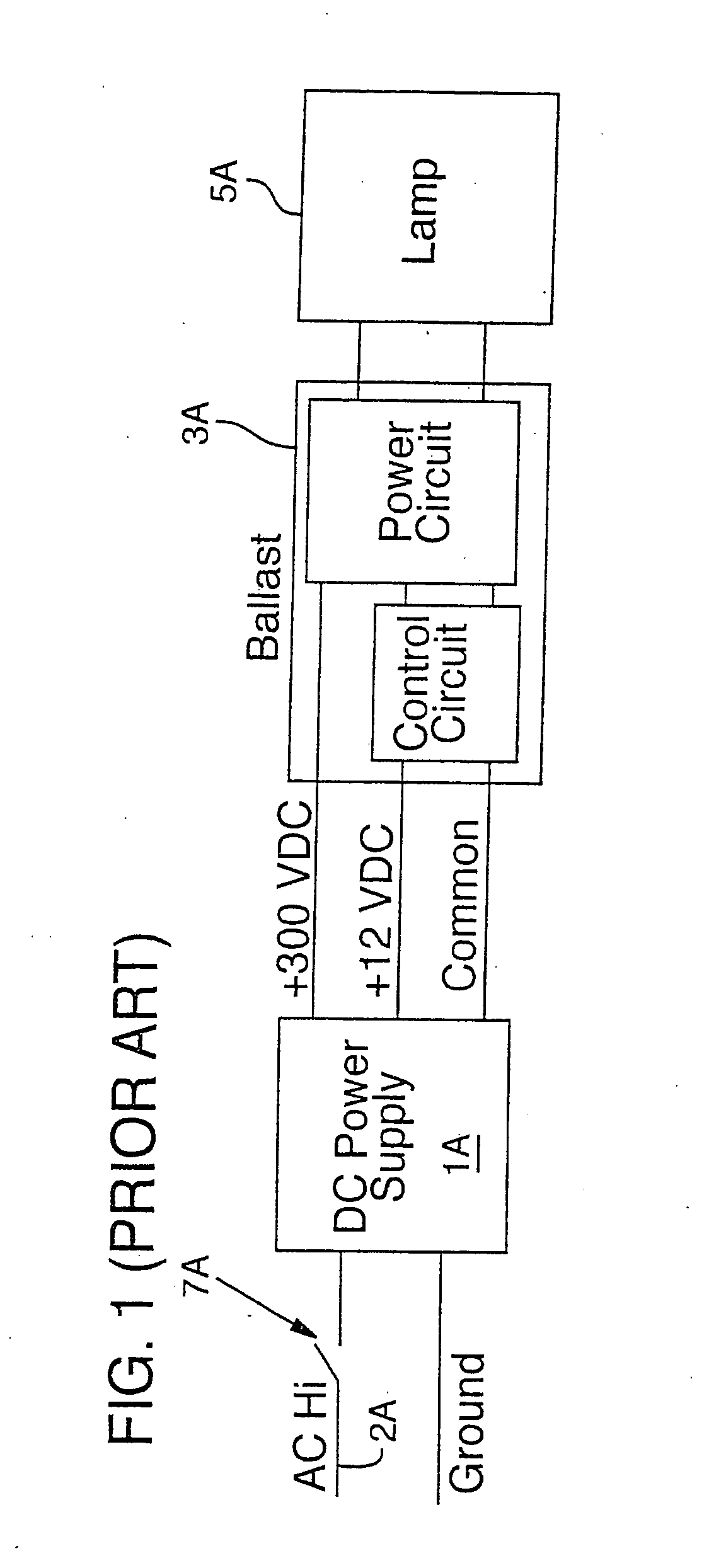
While this prior art approach is effective, interruption of the relatively high voltage AC line power requires a relatively large, expensive safety interlock switch 7A.

Method used


Image

  • Safety interlock apparatus and method
  • Safety interlock apparatus and method
  • Safety interlock apparatus and method

Examples


Embodiment Construction

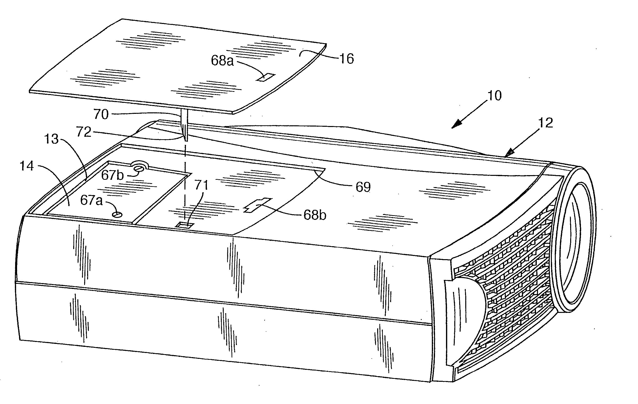
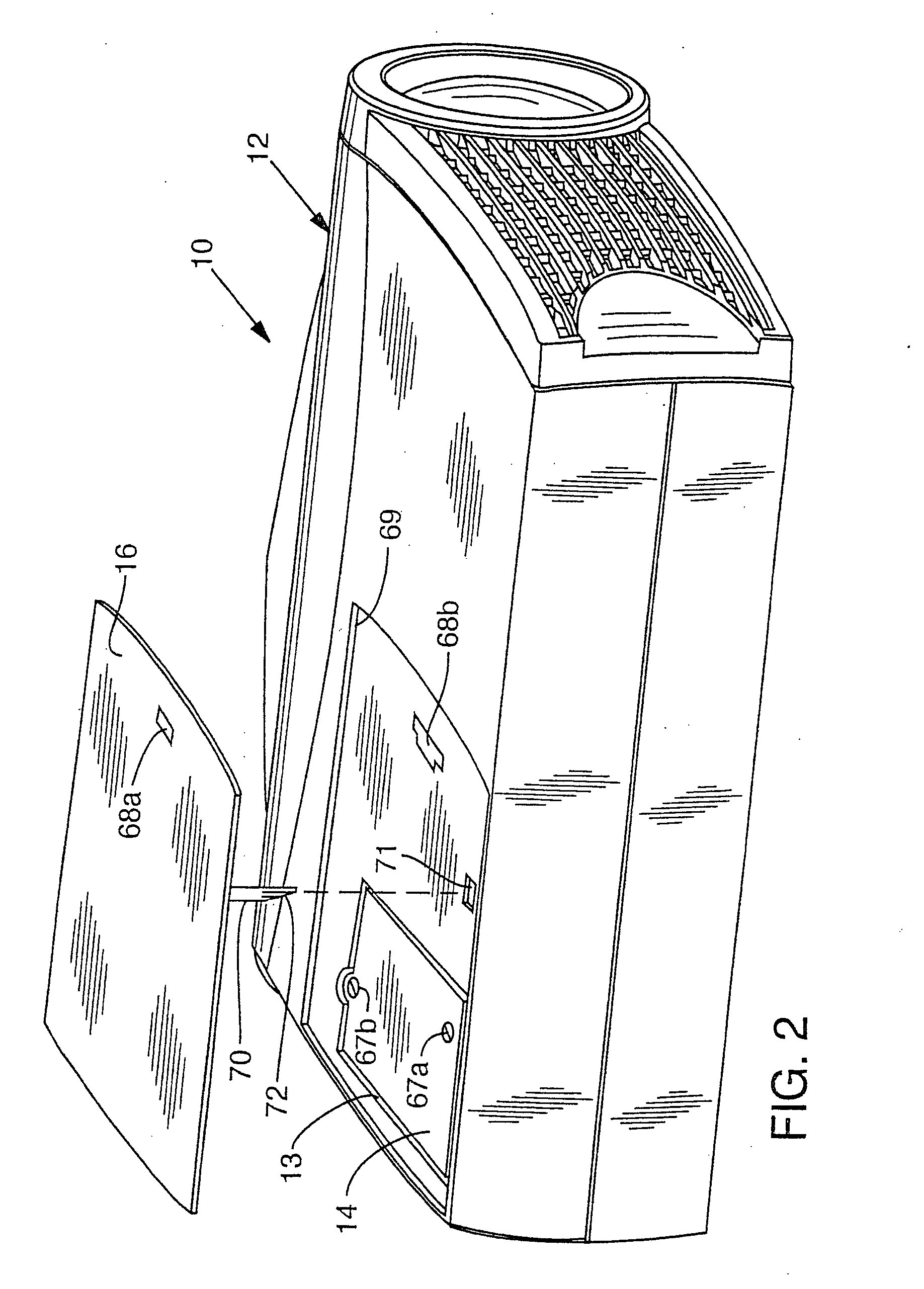
[0023]FIG. 2 shows an image projector 10 (hereafter “projector 10”) in an inverted position. Projector 10 comprises a housing 12 having a lamp module cavity 13, into which a lamp module 14 may be slidably removed or inserted. Cavity 13 is sized to closely mate with lamp module 14, thereby properly aligning and positioning lamp module 14 as it slides into or out of cavity 13. When fully inserted into cavity 13, lamp module 14 is covered by an access panel 16 that snaps into place. The present invention is directed to a safety interlock system that automatically eliminates lamp voltage upon removal of the access panel 16, thereby permitting safe access to the lamp module 14 for removal and replacement.

[0024]FIG. 4 depicts the schematic electrical design of the present safety interlock system 38. A DC power supply 40 receives relatively high voltage alternating current line power (typically ranging from 100 to 230 V AC) from an electrical outlet along line 42. A bridge rectifier 44 re...


PUM


Abstract

A safety interlock apparatus for an electrical device includes a DC power supply, a ballast power supply including a ballast control circuit that controls a ballast power circuit, and a lamp. A relatively low voltage electrical connection is present between the DC power supply and the ballast control circuit. A relatively high voltage electrical connection is present between the lamp and the ballast power circuit. A safety interlock switch is positioned on the relatively low voltage electrical connection, the switch having a closed state wherein the relatively low voltage is supplied to the ballast control circuit and an open disconnected state wherein the relatively low voltage electrical connection is disconnected. A panel is fixable to the electrical device frame, and is selectively movable to expose the lamp for removal. The panel has a switch actuator positioned thereon operable to actuate the interlock switch to the open disconnected state when the panel is removed from the device, thereby disconnecting power to the ballast control circuit, which in turn immediately disables the ballast power circuit, rendering the lamp safe for removal.

Description

RELATED APPLICATIONS [0001] This application is a division of U.S. patent application Ser. No. 09 / 569,541, filed May 12, 2000.COPYRIGHT NOTICE [0002]©2001 InFocus Corporation. A portion of the disclosure of this patent document contains material which is subject to copyright protection. The copyright owner has no objection to the facsimile reproduction by anyone of the patent document or the patent disclosure, as it appears in the Patent and Trademark Office patent file or records, but otherwise reserves all copyright rights whatsoever. 37 CFR § 1.71(d). TECHNICAL FIELD [0003] This invention relates to safety interlock devices and more particularly to an electromechanical interlock connector for supplying power to an arc lamp module and concurrently securing the arc lamp module within an image projector. BACKGROUND OF THE INVENTION [0004] There are previously known safety interlocking systems for protecting electrical equipment users and technicians against hazards, such as electric...

Claims


Application Information

Patent Timeline
Patent Type & Authority Applications(United States)
IPC IPC(8): H05B41/292
CPCH05B41/2925
Inventor PRUETT, HENRY FRAZIERDUFFY, GERALD E.
Owner SEIKO EPSON CORP
Learn More