Systems and methods for achieving low power standby through interaction between a microcontroller and a switching mode power supply

a microcontroller and power supply technology, applied in the field of system and method for achieving low power standby through interaction between a microcontroller and a switching mode power supply, can solve the problems of increasing the power supply, increasing the cost of the circuit, and focusing on reducing the power consumption, so as to reduce the power requirement of the microcontroller, effectively prolong the amount of time the other circuit components can be shut down, and reduce the power consumption of the circuit.

Inactive Publication Date: 2005-02-24
E G O NORTH AMERICA
View PDF4 Cites 60 Cited by
  • Summary
  • Abstract
  • Description
  • Claims
  • Application Information

AI Technical Summary

Benefits of technology

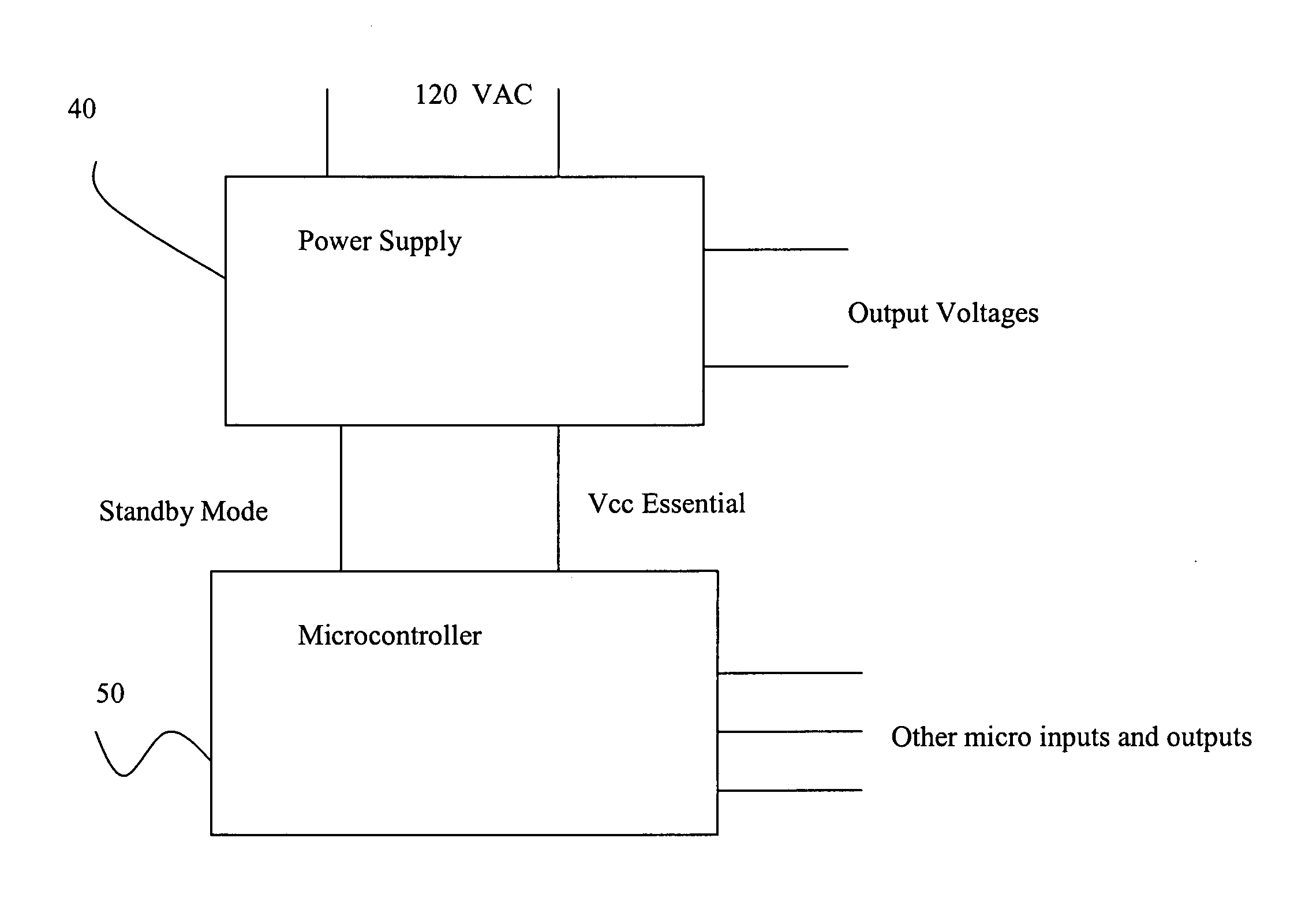
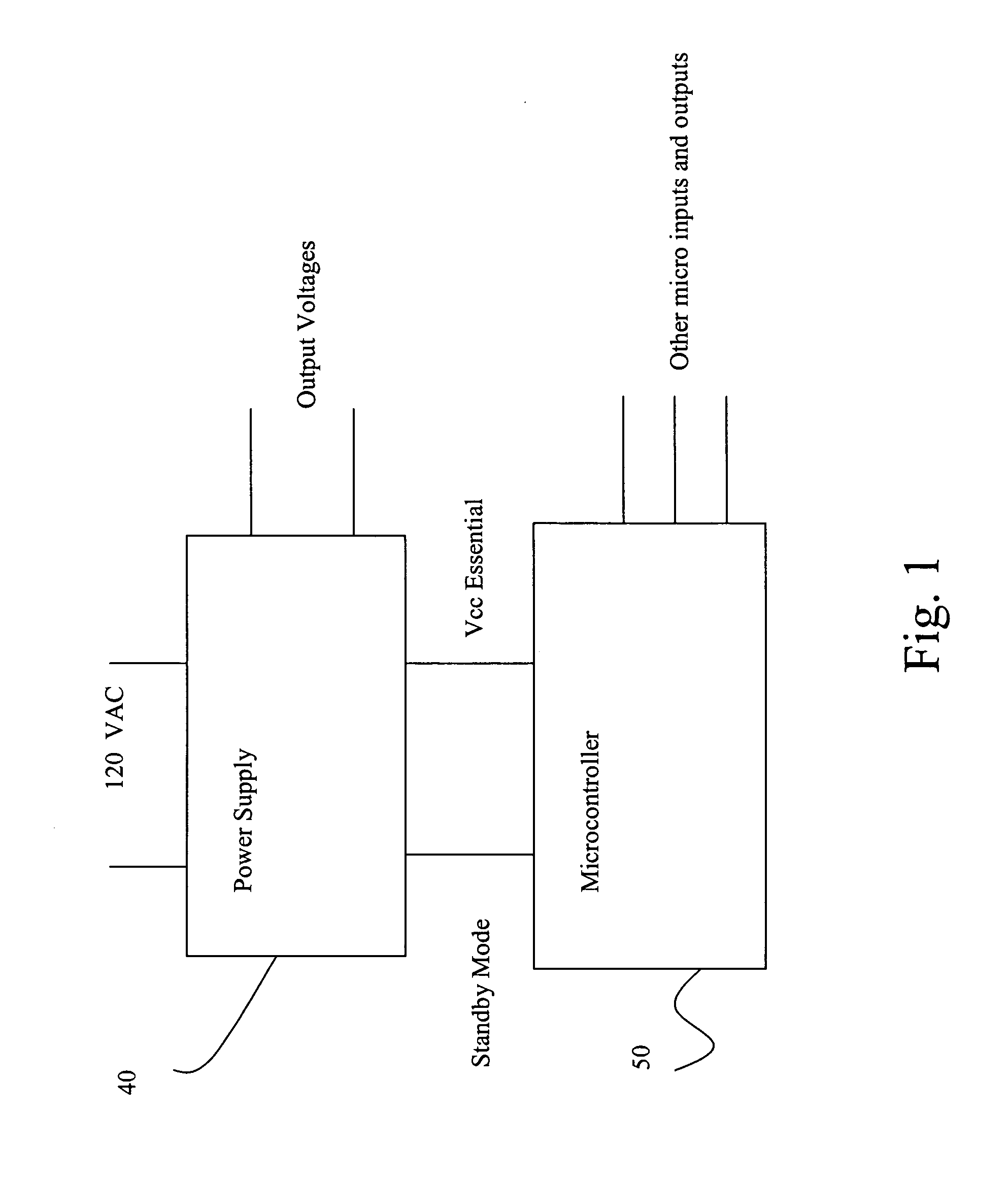
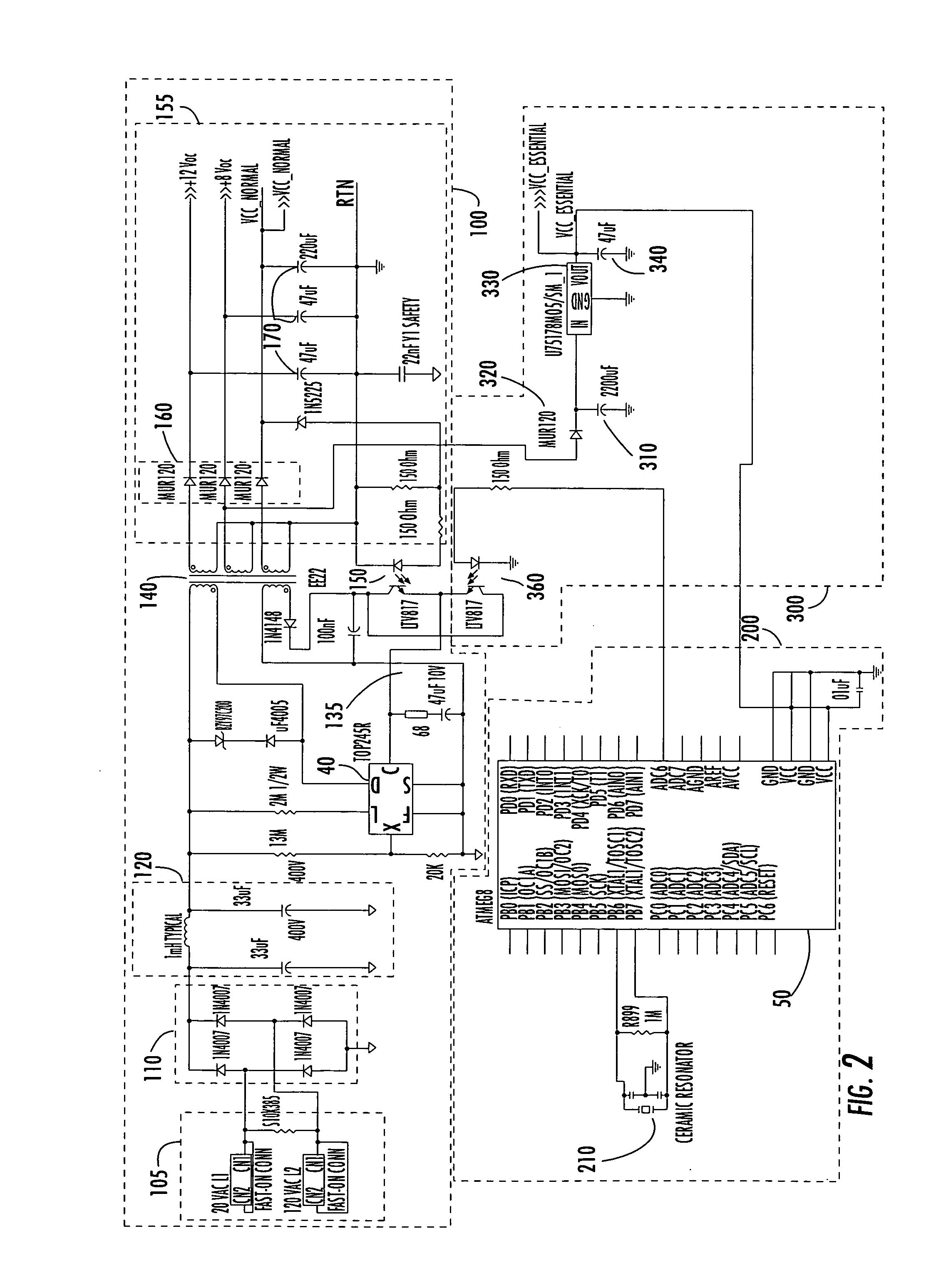
[0007] One embodiment of the present invention discloses using the on-board microcontroller typically found on a control board or power supply board to momentarily turn off a switching mode power supply, placing it in a standby mode. In another embodiment, the power consumption of the circuit is lowered by allowing the power supply and other circuit com

Problems solved by technology

This approach, however, involves a significant amount of expense in that it requires an additional power supply from the main power supply being disabled, as well as a microcontroller to operate the relay.
Other techniques for reducing power supply consumption h

Method used


Image

  • Systems and methods for achieving low power standby through interaction between a microcontroller and a switching mode power supply
  • Systems and methods for achieving low power standby through interaction between a microcontroller and a switching mode power supply
  • Systems and methods for achieving low power standby through interaction between a microcontroller and a switching mode power supply

Examples


Embodiment Construction

[0013] The present invention now will be described more fully hereinafter with reference to the accompanying drawings, in which preferred embodiments of the invention are shown. This invention may, however, be embodied in many different forms and should not be construed as limited to the embodiments set forth herein; rather, these embodiments are provided so that this disclosure will be thorough and complete, and will fully convey the scope of the invention to those skilled in the art. Like numbers refer to like elements throughout.

[0014] Many modifications and other embodiments of the invention will come to mind to one skilled in the art to which this invention pertains having the benefit of the teachings presented in the foregoing descriptions and the associated drawings. Therefore, it is to be understood that the invention is not to be limited to the specific embodiments disclosed and that modifications and other embodiments are intended to be included within the scope of the ap...


PUM


Abstract

An embodiment of the present invention discloses using an on-board microcontroller typically found on a control board or power supply board to momentarily toggle a switching mode power supply off and on. In one embodiment, the power consumption of the circuit is lowered by allowing the power supply and other circuit components to shut down while using a capacitor to provide reserve power to the microcontroller. In another embodiment, the microcontroller is also placed in a low power consumption mode for a predetermined period of time, which decreases the power requirement of the microcontroller and effectively lengthens the amount of time the other circuit components can be shut down. As described herein, this circuitry required to achieve this lower power state is minimal in comparison to known systems and, in one embodiment, requires an optoisolator (or alternatively, a transistor), a resistor and a capacitor.

Description

RELATED APPLICATIONS [0001] This application claims benefit of U.S. provisional patent application No. 60 / 497021, filed Aug. 20, 2003.FIELD OF THE INVENTION [0002] The present invention relates generally to methods and systems that reduce power consumption in electronic devices. More particularly, circuits are described incorporating a microcontroller and switching mode power supply to achieve a low power standby mode in a household kitchen appliance. BACKGROUND OF THE INVENTION [0003] In recent years, the phenomenon of energy wasted from the standby power mode in electrical equipment has become a significant focus of policies directed to energy conservation. Various groups, corporations, as well as various governmental organizations, are exploring ways to reduce standby power consumption in commercial and residential products. In fact, many policies directed to standby power efforts are already in place and apply to specific types of products such as personal computer, televisions ...

Claims


Application Information

Patent Timeline
IPC IPC(8): H02J9/00
CPCH02J9/005Y02B70/16H02M2001/0032Y02B70/10Y04S20/20Y02B70/30H02M1/0032
Inventor DETTWEILER, DAVID A.
Owner E G O NORTH AMERICA
Why Eureka
Try Eureka