Method and apparatus for reducing data burst overhead in an ethernet passive optical network

a passive optical network and data burst technology, applied in the field of design, can solve the problems of increasing the capacity of backbone networks without matching the capacity of access networks, reducing the service life of dsl or cm technology, and reducing the cost of data burst overhead. the effect of reducing the overhead

Inactive Publication Date: 2005-02-24
AVAGO TECH WIRELESS IP SINGAPORE PTE
View PDF13 Cites 67 Cited by
  • Summary
  • Abstract
  • Description
  • Claims
  • Application Information

AI Technical Summary

Benefits of technology

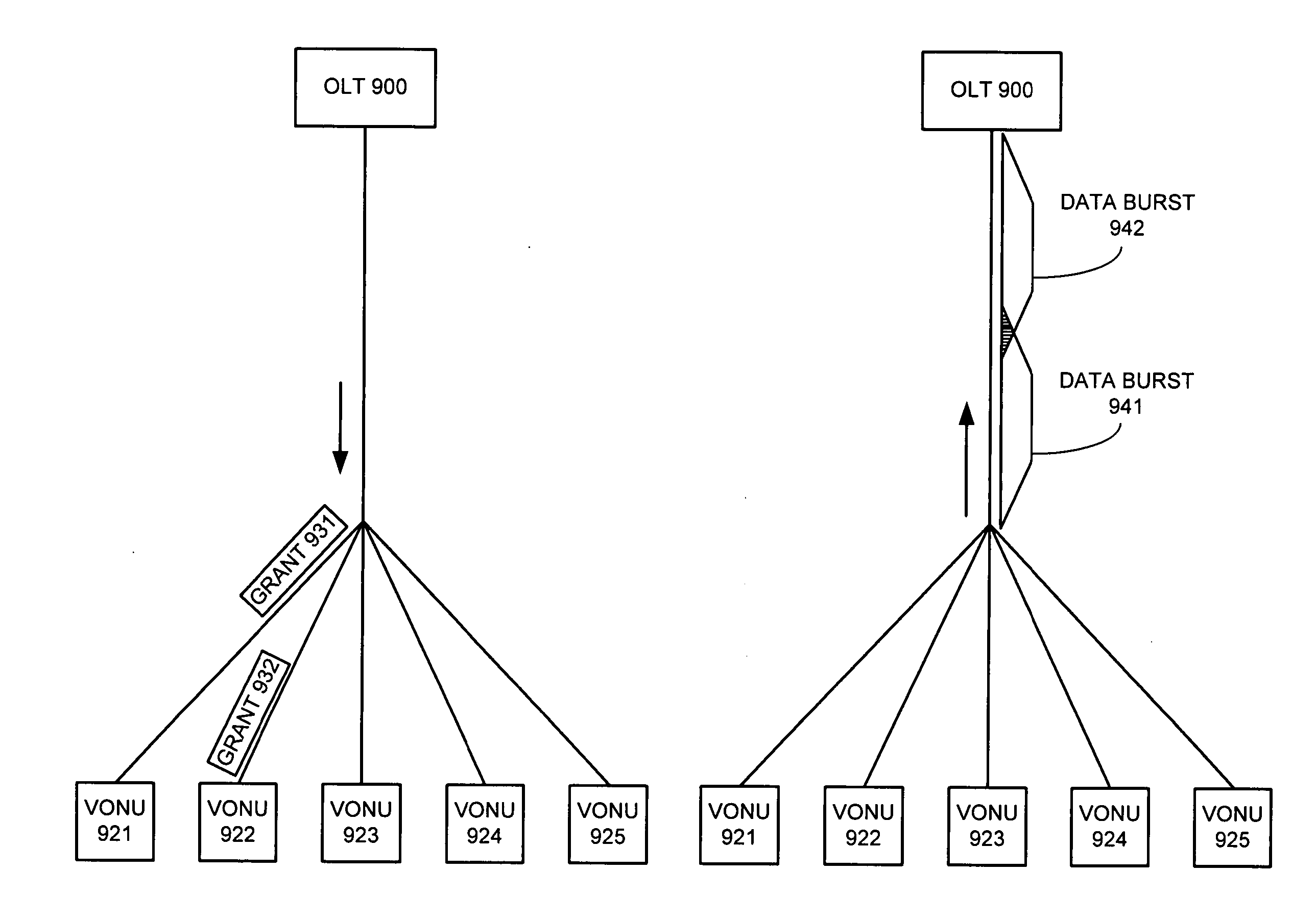
[0014] One embodiment of the present invention provides a system that reduces data burst overhead in an Ethernet passive optical network which includes a central node and at least one remote node, wherein downstream data from the central node is broadcast to the remote nodes, and wherein upstream data from a remote node is transmitted to the central node in a unicast manner. During operation, the central node transmits grant messages to a number of remote nodes, wherein a grant message for a specified remote node assigns a start time and a duration of a transmission timeslot in which the specified remote node may transmit an upstream data burst. In response to the grant messages, the central node then receives a number of upstream data bursts, wherein the time gap between two consecutive upstream data bursts is less than the summation of a default laser turn-on time, a default laser turn-off time, an AGC period, and a CDR period.

Problems solved by technology

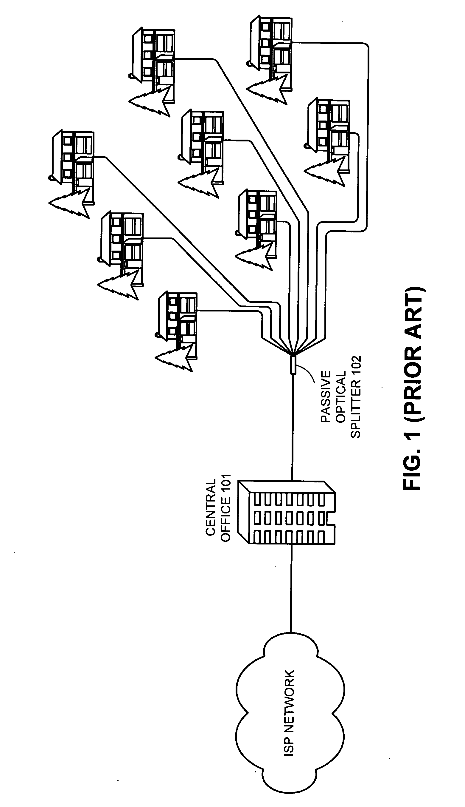
However, this increase in the capacity of backbone networks has not been matched by a corresponding increase in the capacity of access networks.
Even with broadband solutions, such as digital subscriber line (DSL) and cable modem (CM), the limited bandwidth offered by current access networks creates a severe bottleneck in delivering high bandwidth to end users.
Such integrated service is difficult to provide with DSL or CM technology.
Another issue is that it is not enough just to disallow an ONU from sending data outside its assigned transmission timeslot.
Even in the absence of data transmission, an ONU's laser generates spontaneous emission noise when powered on.
This data burst overhead makes the upstream bandwidth utilization less efficient.

Method used


Image

  • Method and apparatus for reducing data burst overhead in an ethernet passive optical network
  • Method and apparatus for reducing data burst overhead in an ethernet passive optical network
  • Method and apparatus for reducing data burst overhead in an ethernet passive optical network

Examples


Embodiment Construction

[0041] The following description is presented to enable any person skilled in the art to make and use the invention, and is provided in the context of a particular application and its requirements. Various modifications to the disclosed embodiments will be readily apparent to those skilled in the art, and the general principles defined herein may be applied to other embodiments and applications without departing from the spirit and scope of the present invention (e.g., general passive optical network (PON) architectures). Thus, the present invention is not intended to be limited to the embodiments shown, but is to be accorded the widest scope consistent with the principles and features disclosed herein.

[0042] The data structures and procedures described in this detailed description are typically stored on a computer readable storage medium, which may be any device or medium that can store code and / or data for use by a computer system. This includes, but is not limited to, applicati...


PUM


Abstract

One embodiment of the present invention provides a system that reduces data burst overhead in an Ethernet passive optical network which includes a central node and at least one remote node, wherein downstream data from the central node is broadcast to the remote nodes, and wherein upstream data from a remote node is transmitted to the central node in a unicast manner. During operation, the central node transmits grant messages to a number of remote nodes, wherein a grant message for a specified remote node assigns a start time and a duration of a transmission timeslot in which the specified remote node may transmit an upstream data burst. In response to the grant messages, the central node then receives a number of upstream data bursts, wherein the time gap between two consecutive upstream data bursts is less than the summation of a default laser turn-on time, a default laser turn-off time, an AGC period, and a CDR period.

Description

RELATED APPLICATION [0001] This application hereby claims priority under 35 U.S.C. §119 to U.S. Provisional Patent Application No. 60 / 495,649 filed on 13 Aug. 2003, entitled “Method for Timeslot Allocation to Reduce Guard Band Overhead in Ethernet Passive Optical Networks,” by inventor Glen Kramer.BACKGROUND [0002] 1. Field of the Invention [0003] The present invention relates to the design of Ethernet passive optical networks. More specifically, the present invention relates to a method and apparatus for reducing data burst overhead in an Ethernet passive optical network. [0004] 2 Related Art [0005] In order to keep pace with increasing Internet traffic, optical fibers and associated optical transmission equipment have been widely deployed to substantially increase the capacity of backbone networks. However, this increase in the capacity of backbone networks has not been matched by a corresponding increase in the capacity of access networks. Even with broadband solutions, such as d...

Claims


Application Information

Patent Timeline
Patent Type & Authority Applications(United States)
IPC IPC(8): H04B10/272H04J3/06H04J3/16H04Q11/00
CPCH04J3/0682H04Q2011/0064H04Q11/0067H04B10/27H04J3/06H04J3/16
Inventor KRAMER, GLEN
Owner AVAGO TECH WIRELESS IP SINGAPORE PTE
Why Eureka
Try Eureka