Optical fiber connection utilizing fiber containing ferrules

Active Publication Date: 2005-02-24
FURAKAWA ELECTRIC NORTH AMERICA INC
View PDF5 Cites 8 Cited by
  • Summary
  • Abstract
  • Description
  • Claims
  • Application Information

AI Technical Summary

Benefits of technology

[0015] In a second embodiment of the invention, the ID of the sleeve in its secondary state is profiled to have an enlarged portion at the rear of the sleeve and a “gripping” or clamping portion at the front portion, which, when returned to the primary or initial state, grips the fiber firmly at the front of the ferrule but leaves some “slop” at the rear thereof. This facilitates insertion and withdrawal of the fiber.
[0016] In still another embodiment of the invention, the central bore of the ferrule molded of zirconia-ceramic has opposed longitudinally extending hollow lobes rather than a secondary cylindrical capillary tube. Within the bore are first and second V-shaped NTA members, the V-shape being the secondary configuration of the NTA memb

Problems solved by technology

This is a production process for manufacturing ferrules, and is unsuitable for use in the field.
Adhesives and cements are messy to handle and can also contaminate the precision outside surface

Method used


Image

  • Optical fiber connection utilizing fiber containing ferrules
  • Optical fiber connection utilizing fiber containing ferrules
  • Optical fiber connection utilizing fiber containing ferrules

Examples


Embodiment Construction

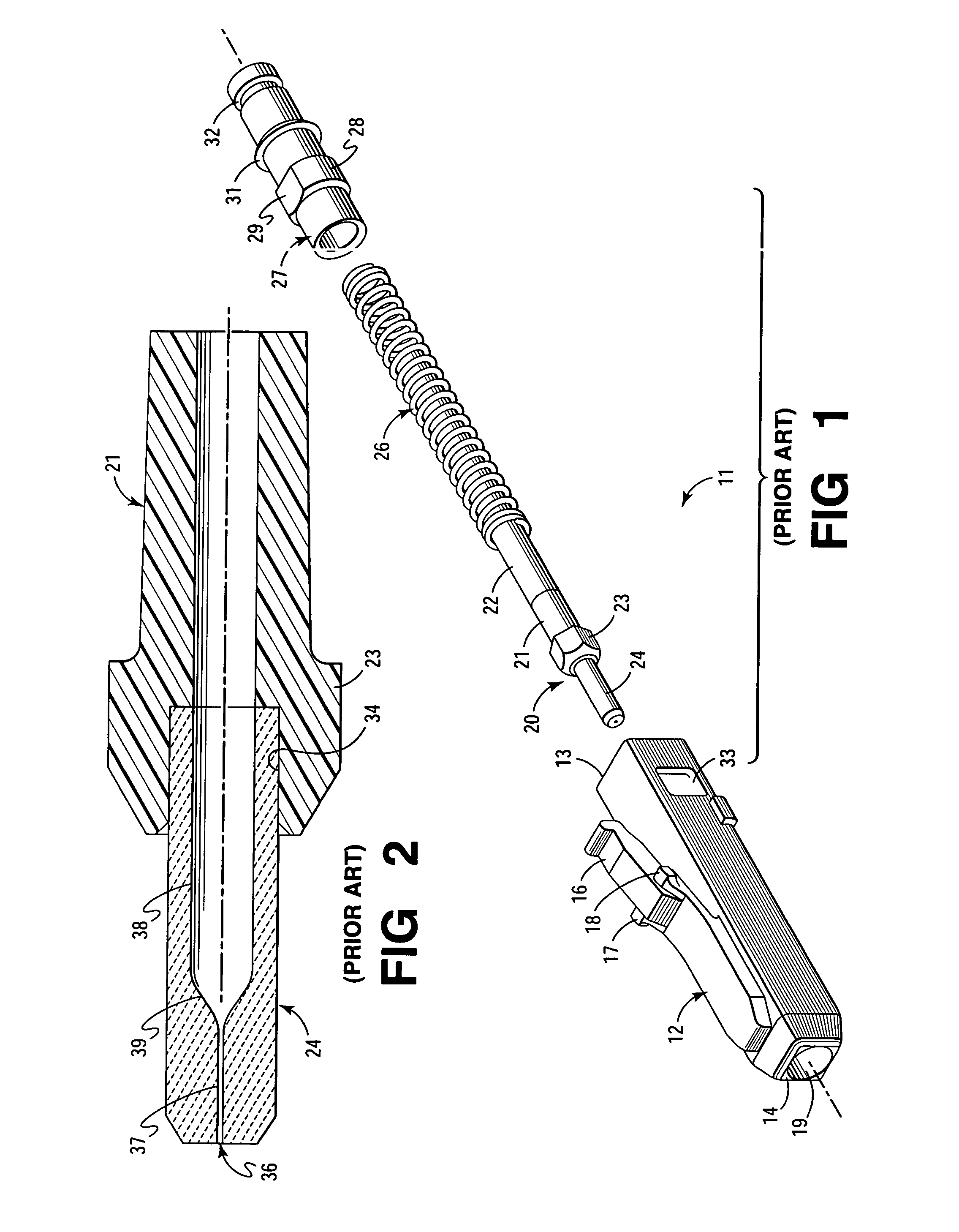
[0035]FIG. 1 is an exploded perspective view of a prior art plug connector 11 of the LC type to illustrate the location of the ferrule 24. Although an LC type connector is shown, the invention is applicable to any of a large number of connector types. Connector 11 comprises a housing 12 having a cable entrance end 13 and a ferrule end 14. A latching arm 16 which has first and second latching lugs 17 and 18 extends from housing 12, and functions to latch the plug connector 11 in place. Housing 12 and arm 16 are preferably made of a suitable plastic material which has sufficient resilience to allow the latching arm 16 to be depressed for insertion and to spring back into its latching position.

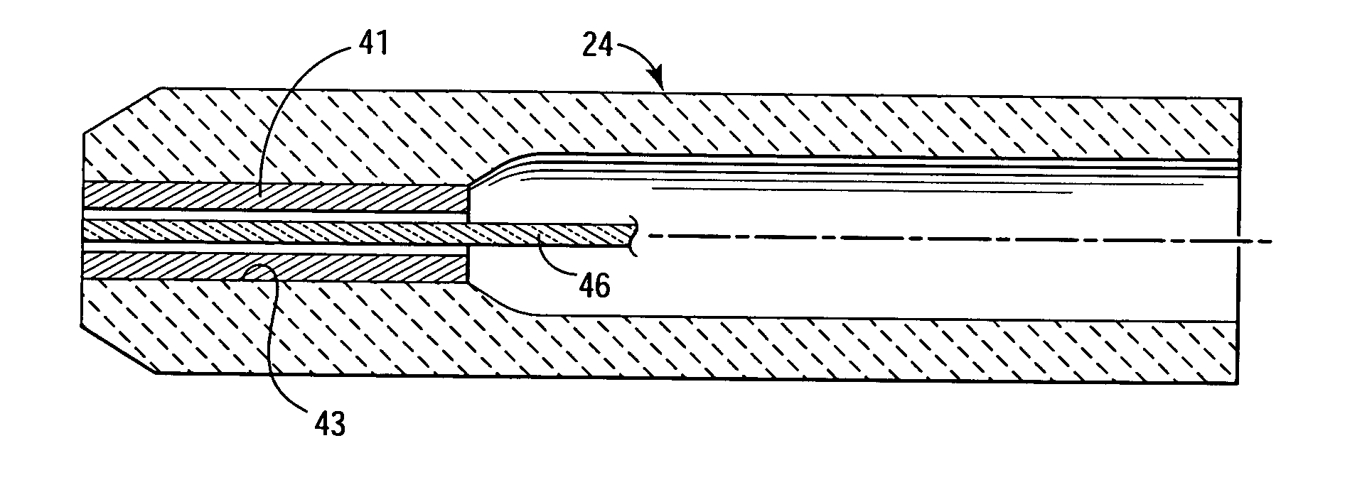
[0036] Housing 12 has an axial bore 19 extending therethrough which accommodates a ferrule-barrel assembly 20. Assembly 20 comprises a flexible hollow tubular member 22 attached to a metal or hard plastic barrel member 21 with an enlarged flange 23 from which extends a ferrule 24 which may be of...


PUM


Abstract

A ferrule for use in optical fiber connections has an optical fiber containing a bore extending therethrough. Within the bore is a member of shaped memory alloy (SMA) which clamps and affixes the fiber firmly in place within the ferrule without the necessity of cementing the fiber in place. The shaped memory alloy has two states: the initial or primary state and the secondary or deformed state. In the embodiments of the invention, the member is deformed from the initial state to the secondary state and the fiber is inserted in the ferrule. The member is then returned to the primary state in which it firmly clamps the fiber within the ferrule.

Description

FIELD OF THE INVENTION [0001] This invention relates to optical fiber connectors, and more particularly, to such connectors having fiber containing ferrules. BACKGROUND OF THE INVENTION [0002] In optical fiber communications, connectors for joining fiber segments at their ends, or for connecting optical fiber cables to active or passive devices, are an essential component of virtually any optical fiber system. The connector or connectors, in joining fiber ends, for example, has, as its primary function, the maintenance of the fiber ends in a butting relationship such that the core of one of the fibers is axially aligned with the core of the other fiber so as to maximize light transmissions from one fiber to the other. Another goal is to minimize back reflections. Such alignment is extremely difficult to achieve, which is understandable when it is recognized that a fiber is 125.0±0.5 microns and that the mode field diameter, of, for examples, a singlemode fiber is approximately nine ...

Claims


Application Information

Patent Timeline
IPC IPC(8): G02B6/36G02B6/38
CPCG02B6/3859
Inventor LAMPERT, NORMAN R.
Owner FURAKAWA ELECTRIC NORTH AMERICA INC
Why Eureka
Try Eureka