
Multipath distortion eliminating filter

a filter and multi-path technology, applied in adaptive networks, complex mathematical operations, instruments, etc., can solve the problems of deteriorating reproduction sound quality, noise suppression achieved at the cost of sound quality of some sort, and methods thus far from achieving substantial elimination of multi-path distortion, so as to eliminate multi-path distortion with reliability, improve operation accuracy, and minimize the effect of errors detected

Inactive Publication Date: 2005-02-24
PIONEER CORP
View PDF12 Cites 3 Cited by
  • Summary
  • Abstract
  • Description
  • Claims
  • Application Information

AI Technical Summary

Benefits of technology

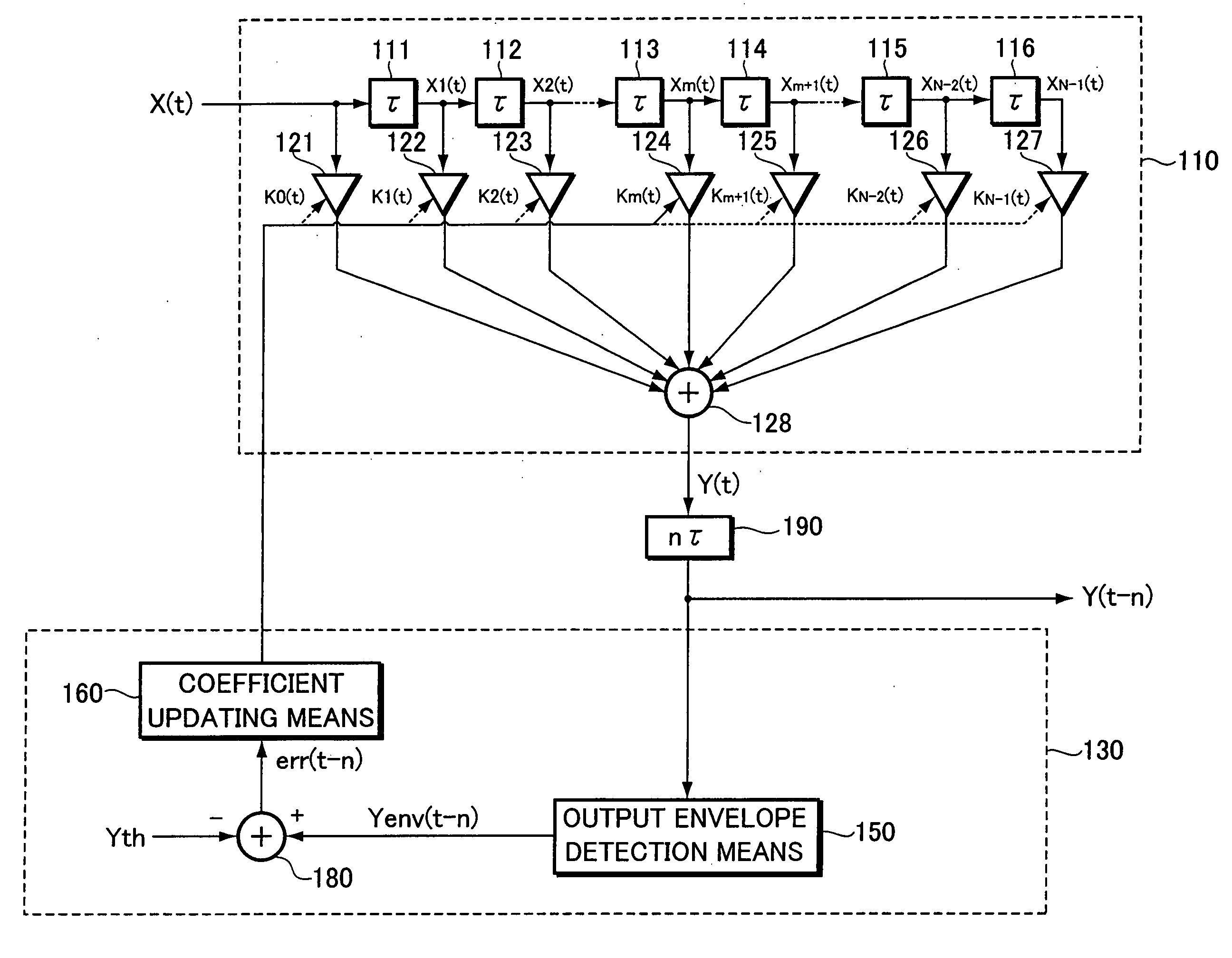
The present invention provides a filter that can improve the operation accuracy and eliminate distortion caused by multiple paths. The filter uses a digital filter with a plurality of coefficient multipliers to apply a filter operation processing to a digital reception signal. The filter also includes error detection means to detect any errors between the output signal and a reference value. The filter characteristic is predicted and computed to minimize the error, and the tap coefficients of the filter are updated based on the computed result. The filter also has a delay circuit in the output stage. This invention can improve the performance of FM receivers and make them more reliable.

Problems solved by technology

Among problems of importance in FM radio broadcasts is interference that caused by multipath-based distortion (hereinafter referred to as “multipath distortion”) of the reception waves.
The multipath distortion may cause pulsed noise in FM demodulation signals, contributing to a deterioration in reproduction sound quality.
In the methods of reducing noise through ARC control and the like, however, the noise suppression has been achieved at the cost of sound quality of some sort, including the stereophonic feel of the demodulated sound.
These methods have thus been far from achieving substantial elimination of the multipath distortion.
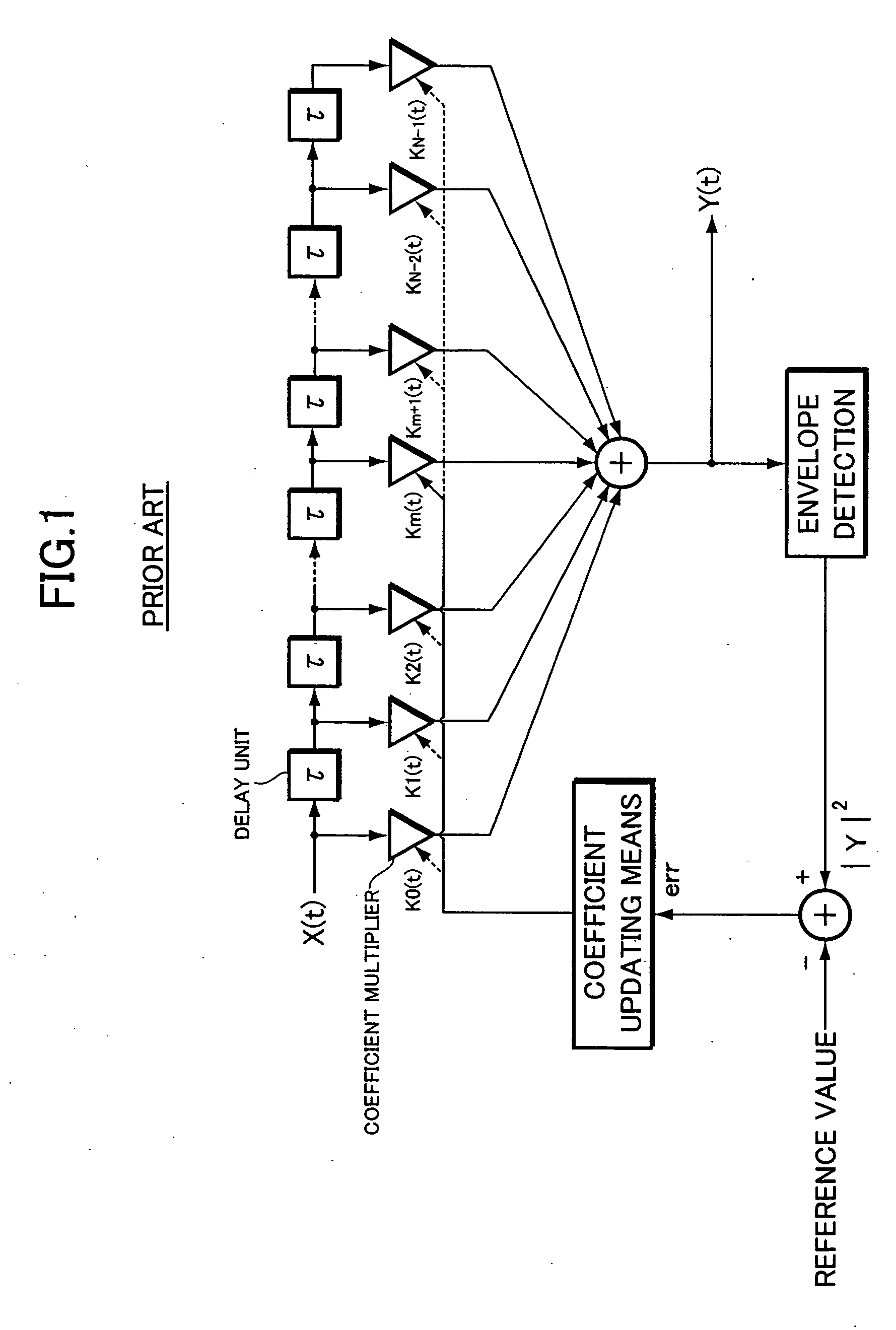
However, since an operation load for updating the tap coefficient Km is heavy, an entire operation time for the adaptive filter is subject to the foregoing operation load.
In other words, it was difficult for the conventional adaptive filter to improve the arithmetic processing accuracy according to the reasons of having a long critical path, being impossible to set a high reference clock in a digital operation processing, and the like.

Method used


Image

  • Multipath distortion eliminating filter
  • Multipath distortion eliminating filter
  • Multipath distortion eliminating filter

Examples


Embodiment Construction

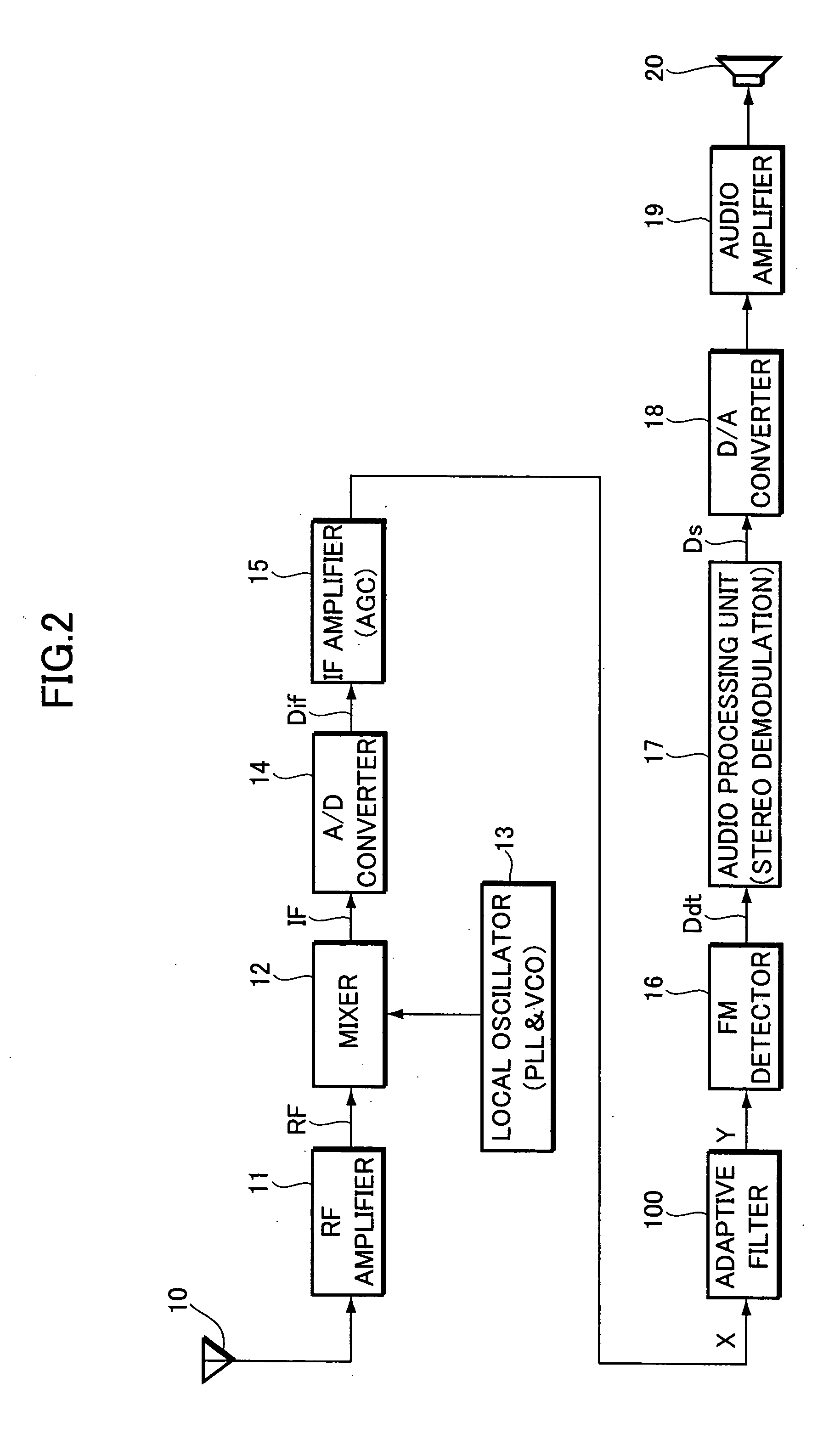
Hereinafter, a most preferred embodiment of the present invention will be described with reference to the drawings. Description will initially be given of an FM receiver on which an adaptive filter 100 according to the present embodiment is mounted. FIG. 2 is a block diagram showing the configuration of a digital FM receiver such as a car radio.

In the diagram, the FM-broadcast reception wave received by an antenna circuit 10 is amplified by an RF amplifier (radio frequency amplifier) 11. The resulting RF signal is output to a mixer 12. The mixer 12 mixes the RF signal with a local oscillation signal from a local oscillator 13, which is composed of a PLL circuit, a VCO circuit, etc. An intermediate frequency signal IF of downconverted frequency is thus generated, and supplied to an A / D converter 14. The A / D converter 14 converts the intermediate frequency signal IF, an analog signal, into a digital sample value signal (hereinafter referred to as “digital signal”) Dif at predetermi...


PUM


Abstract

An adaptive filter for an FM receiver comprises a digital filter, an error detection section for detecting an error between the output amplitude of the digital filter and a reference value, and a coefficient updating section for updating tap coefficients so as to minimize the detected error. Further, a delay circuit is provided in an output stage of the digital filter so as to reduce an operation load. Thus, the adaptive filter can improve an operation accuracy of the digital filter, thereby eliminating multipath distortion with reliability.

Description

BACKGROUND OF THE INVENTION The present invention relates to a multipath distortion eliminating filter which is mounted on an FM receiver to eliminate multipath-based distortion occurring in reception waves. The present application claims priority from Japanese Patent Application No.2003-207868, the disclosure of which is incorporated herein by reference. Among problems of importance in FM radio broadcasts is interference that caused by multipath-based distortion (hereinafter referred to as “multipath distortion”) of the reception waves. The multipath distortion is the phenomenon that an FM reception wave signal, which should basically have a constant amplitude, varies in amplitude because of mutual interference between a plurality of incoming waves having different phases and different field intensities due to multiple wave propagation. In particular, FM receivers mounted on mobile units, such as a car radio, is sometimes subject to multipath distortion with sharp fluctuations i...

Claims


Application Information

Patent Timeline
Patent Type & Authority Applications(United States)
IPC IPC(8): H03H17/02H03H17/06H03H21/00H04B1/10H04B1/26
CPCH03H21/0012
Inventor YAMAMOTO, YUJIKUBUKI, TOSHIAKI
Owner PIONEER CORP
Learn More