Elastic connecting duct

a technology of elastic connecting ducts and connecting ducts, which is applied in the direction of combustion-air/fuel-air treatment, machine/engine, fuel air intakes, etc., can solve the problems of low weight of tools, achieve good thermal decoupling, easy to manufacture, and high stability of core materials

Inactive Publication Date: 2005-03-03
ANDREAS STIHL AG & CO KG
View PDF12 Cites 26 Cited by
  • Summary
  • Abstract
  • Description
  • Claims
  • Application Information

AI Technical Summary

Benefits of technology

[0005] Since a single connecting duct contains both a conduit for fuel / air mixture and a conduit for largely fuel-free air, there is no need for multiple components, connecting ducts or elements to make the connection to the carburetor. It is simply necessary to fit a single connecting duct. This reliably prevents any short circuit between the two conduits. There is no need for a separate channel for the supply of largely fuel-free air. The design of the two channels as separate conduits effects the permanent, vibration-decoupled bridging of the vibration gap between the air filter and the internal combustion engine. The design of the connecting duct and the two conduits in one piece results in a tool of low weight.
[0013] In order to achieve low flow resistance and in particular to prevent the condensation of fuel on the internal wall of the conduit in the mixture duct, the conduits have a seam-free internal wall. The connecting duct expediently has a pulse duct. The pulse duct is in particular designed in the wall of a conduit. The conduits are advantageously made of an elastomer tailored to the thermal specification, in particular a fluorine elastomer or a hydrated nitrile butadiene rubber. The connecting duct is designed as an elastomeric pre-form with a duroplastic insert which is held positively in the elastomeric pre-form. This eliminates the need for the application of bonding agents and primers to the insert in order to provide a bond.

Problems solved by technology

The design of the connecting duct and the two conduits in one piece results in a tool of low weight.

Method used


Image

  • Elastic connecting duct
  • Elastic connecting duct
  • Elastic connecting duct

Examples


Embodiment Construction

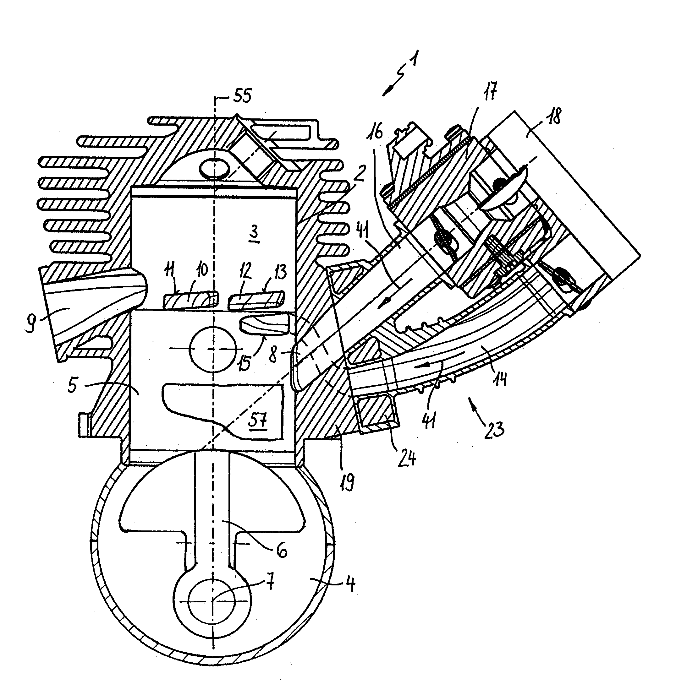
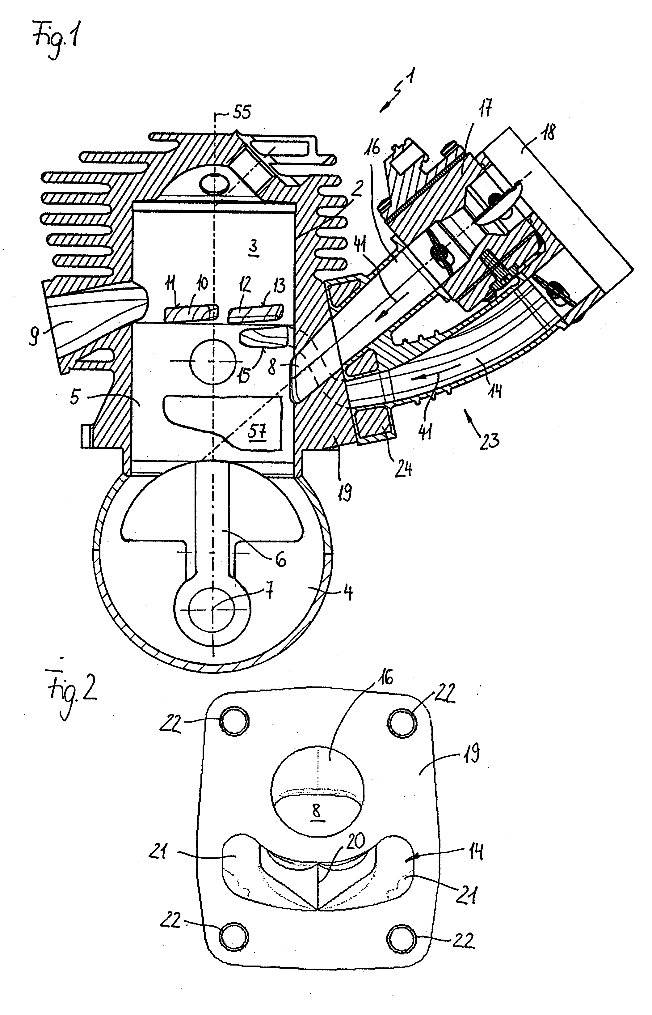
[0035] The two-cycle engine 1 illustrated in FIG. 1 has a cylinder 2 containing a combustion chamber 3. The combustion chamber 3 is delimited by a piston 5 which travels up and down and which drives a crankshaft 7 mounted in a crankcase 4 via a connecting rod 6. The two-cycle engine 1 has an inlet 8 for the supply of fuel / air mixture and an outlet 9 for the discharge of exhaust emissions from the combustion chamber 3. In pre-set piston 5 positions, the crankcase 4 is connected to the combustion chamber 3 via transfer passages 10, 12. In this arrangement there are two transfer passages 10 positioned near the outlet 9 which flow into the combustion chamber 3 at transfer windows 11 and two transfer passages 12 located some distance from the outlet 9 which flow into the combustion chamber 3 at transfer windows 13. Here the transfer passages are positioned symmetrically in relation to a central plane which comprises the longitudinal axis 55 of the cylinder and separates the inlet 8 and t...


PUM

PropertyMeasurementUnit
distanceaaaaaaaaaa
distanceaaaaaaaaaa
elasticaaaaaaaaaa

Abstract

A one-piece elastic connecting duct for disposition between any air filter and an internal combustion engine of a manually operated implement, such as a power saw, a cut-off machine, or the like, is provided. The connecting duct comprises a first conduit for fuel / air mixture, and a second conduit for largely fuel-free air.

Description

BACKGROUND OF THE INVENTION [0001] The invention relates to an elastic connecting duct between an air filter and an internal combustion engine of a manually operated implement such as a power chain saw, a cut-off machine, or the like, whereby the connecting duct is a monolithic component. [0002] A connecting duct which connects the carburetor of a manually operated implement to the combustion chamber of the internal combustion engine is known from U.S. Pat. No. 4,711,225. In order to improve the exhaust emission specifications of a two-cycle engine largely fuel-free air is advanced in the transfer passages in a known process. The air advanced in the transfer passages must then be fed from the air filter to the two-cycle engine. In known two-cycle engines this tales place via separate lines. They each have a connecting duct or another element to bridge the vibration gap between the air filter and the internal combustion engine. This results in tool of complex design and complex assem...

Claims


Application Information

Patent Timeline
Patent Type & Authority Applications(United States)
IPC IPC(8): F02B25/22F02B63/02F02B75/02F02M35/10F02M35/108
CPCF02B25/22F02B2075/025F02M35/10072F02M35/10078F02M35/10118F05C2225/08F02M35/1019F02M35/10321F02M35/10347F02M35/108F02M35/1017
Inventor SCHMIDT, OLAFHILLER, CHRISTOPH V.FRIEDRICH, REINHARDJOOS, MICHAELKERN, JENSSCHLESSMANN, HELMUT
Owner ANDREAS STIHL AG & CO KG
Why Eureka
Try Eureka