Internal Combustion Engine Having an Elastic Connecting Duct

a technology of connecting duct and internal combustion engine, which is applied in the direction of combustion engine, machine/engine, fuel air intake, etc., can solve the problem of low weight of tools, achieve good thermal decoupling, easy to manufacture, and high stability of core materials

Active Publication Date: 2009-12-24
ANDREAS STIHL AG & CO KG
View PDF15 Cites 16 Cited by
  • Summary
  • Abstract
  • Description
  • Claims
  • Application Information

AI Technical Summary

Benefits of technology

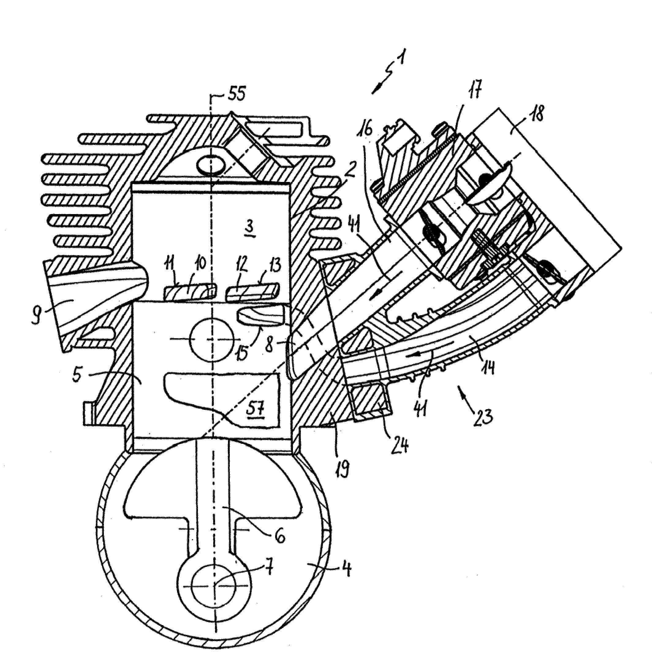
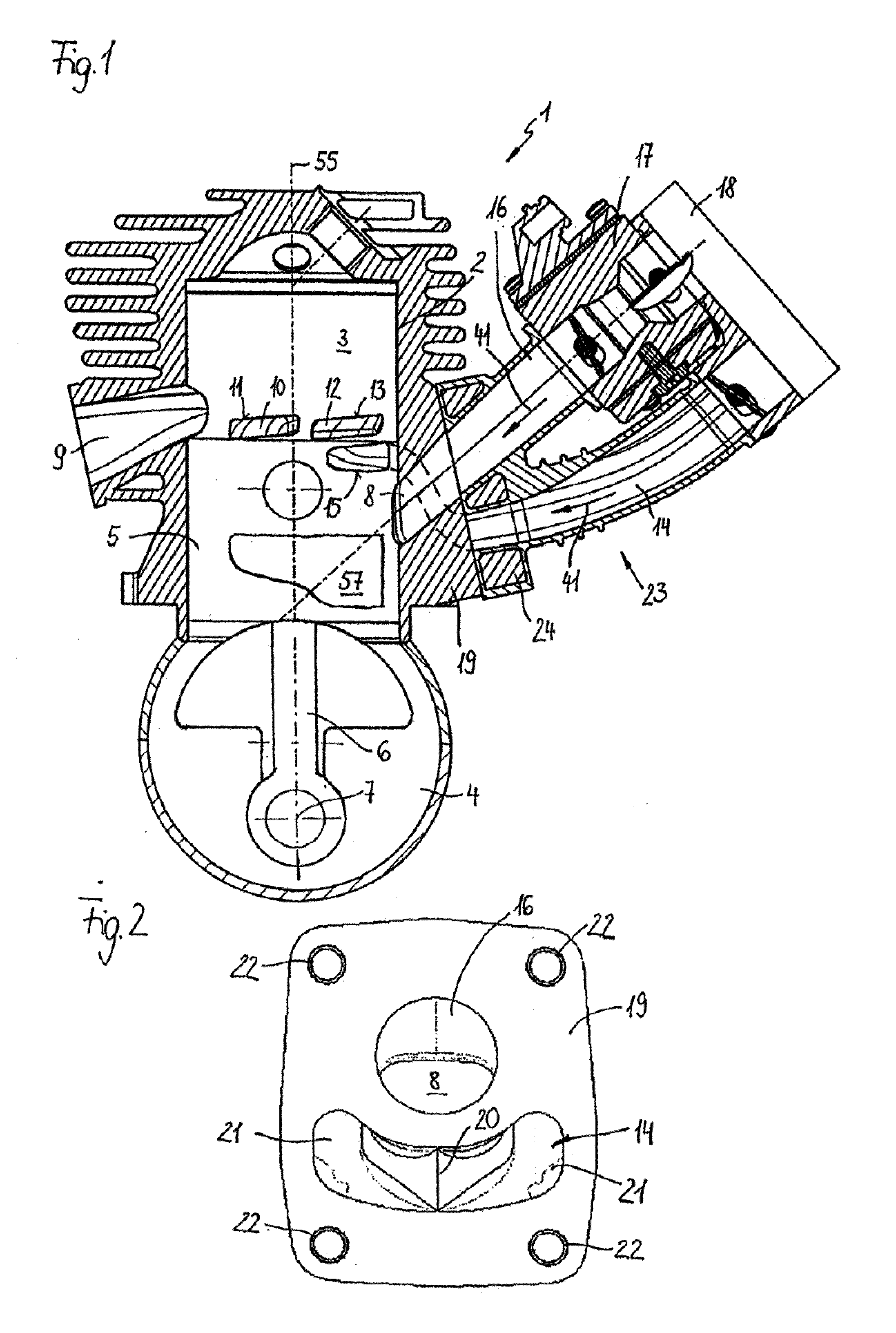
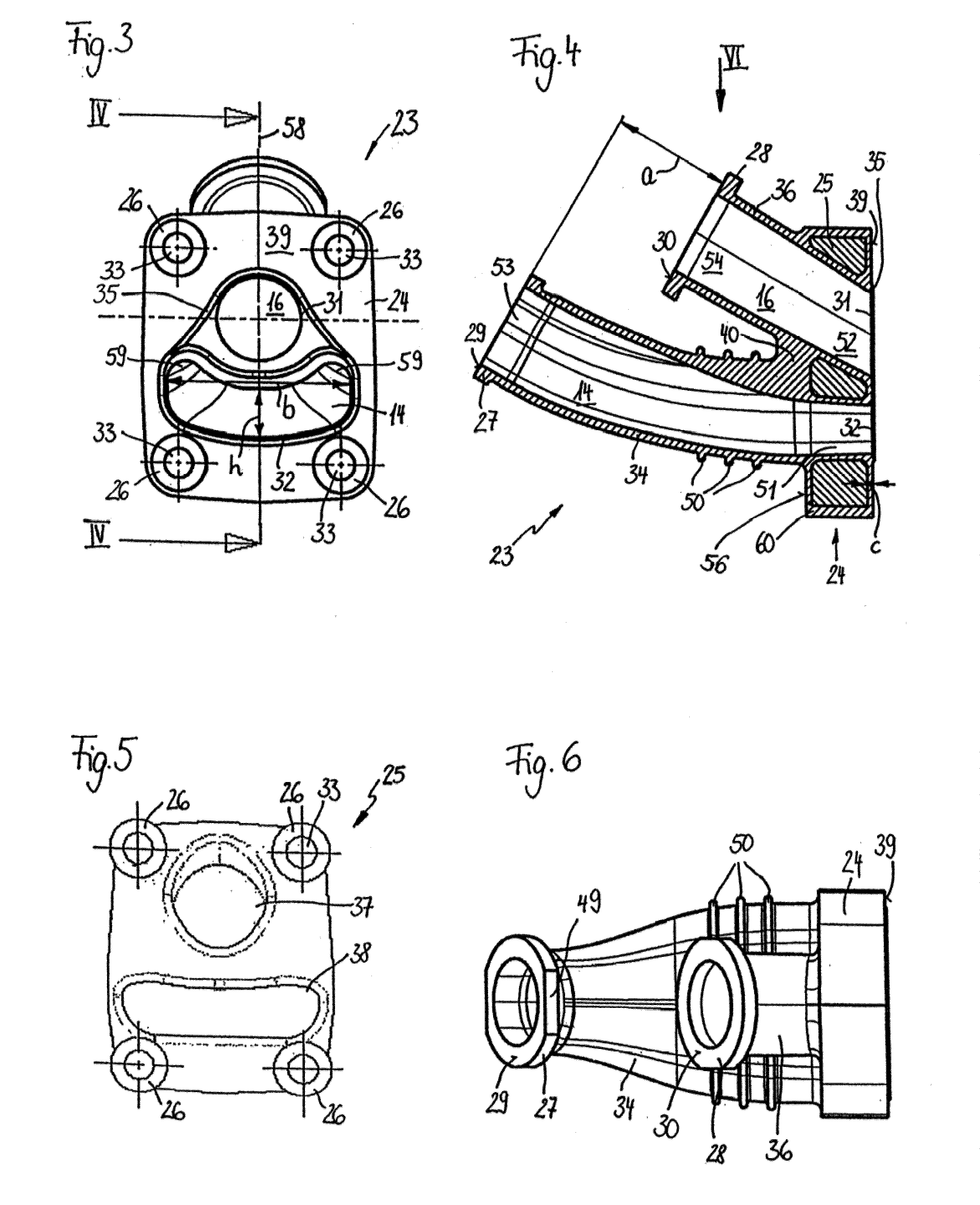
[0009]The core is made in particular from a duroplastic. By extrusion-coating the core, the core is positively connected to the conduits. Since the conduits are connected to one another by the elastic material of the conduits or by the core material, good thermal decoupling is achieved. It may, however, be expedient for the core to be made of metal, in particular steel. The core advantageously takes the form of a plate which is curved towards the flange plane in the area of the fixing openings. A plate core can easily be manufactured in a cost-effective manner. Due to the high stability of the core material, the connecting flange can be thin. Curving the core towards the flange plane in the area of the fixing openings creates a direct connection between the core and the flange of the internal combustion engine in the area of the fixing openings without an intermediate layer of plastic. This enables a defined pressure to be achieved at the bearing surface. At the same time it also produces a stable screw connection.
[0010]In order to achieve a good seal between the connecting flange and the internal combustion engine and between the mixture duct and the air duct, it may also be expedient to form a sealing contour on the connecting plane facing the internal combustion engine. This eliminates the need for additional sealing elements, thereby further simplifying both manufacture and fitting. The sealing contour is advantageously designed as a sealing bead positioned in a groove. The compressed sealing bead is able to expand into the groove when it comes into contact with the flange of the cylinder, thereby achieving a good seal.
[0011]Both conduits expediently have plane-parallel flange planes at the ends facing away from the connecting flange. This means that the two ducts can be fixed easily to the air filter base. In this arrangement, the flange planes are positioned in particular a certain distance apart, the first conduct advantageously being shorter than the second. Here the first conduit is advantageously connected to a carburetor. In this arrangement, the distance between the two flange planes is in particular dimensioned such that once the first conduit has been fitted to the carburetor the connections of the various ducts lie in one plane.
[0012]The first conduit advantageously has an approximately circular flow cross-section which tapers in particular in the direction of flow. This provides a good transition from the circular flow cross-section of the carburetor to the generally slightly elliptical flow cross-section at the inlet to the cylinder of the internal combustion engine. In order to achieve an even flow speed in the conduits, the flow cross-section is largely identical over the entire length of the mixture duct. T

Problems solved by technology

The design of the connecting duct and the two cond

Method used


Image

  • Internal Combustion Engine Having an Elastic Connecting Duct
  • Internal Combustion Engine Having an Elastic Connecting Duct
  • Internal Combustion Engine Having an Elastic Connecting Duct

Examples


Embodiment Construction

[0037]Referring now to the drawings in detail, as an exemplary embodiment of a manually operated implement, FIG. 21 shows a power or chain saw 61. The chain saw 21 has a housing 62 to which a handle frame 66 is secured by means of a plurality of anti-vibration elements 67, so that the handle frame 66 is uncoupled or isolated from the housing 62 with regard to vibration. A vibration gap 70 is formed between the handle frame 66 and the housing 62. The vibration gap 70 permits relative movements between the handle frame 66 and the housing 62, so that movements of the housing 62 that result from vibrations that occur during operation are not transferred, or are transferred only partially, to the handle frame 66. The handle frame 66 includes a rear handle 72, and a tubular handle 73. Connected with the handle frame 66, adjacent to the rear handle 72 are an operating medium tank 69, for example a fuel tank, and an air filter compartment 71. The air filter compartment 71 can also be connec...


PUM

PropertyMeasurementUnit
Lengthaaaaaaaaaa
Widthaaaaaaaaaa
Heightaaaaaaaaaa

Abstract

An internal combustion engine of a manually operated implement, having an elastic connecting duct between the engine and an air filter for vibration-decoupled bridging of a vibration gap between engine and the air filter. The elastic connecting duct has a first conduit for fuel/air mixture and a second conduit for largely fuel-free air. The first and second conduits are separate tubes having respective bores that are separated from one another over their entire lengths, the inlet of the engine is operatively connected to the air filter via the first conduit, and an air duct window of the engine is operatively connected to the air filter via the second conduit.

Description

CROSS-REFERENCE TO RELATED APPLICATIONS[0001]This application is a continuation-in-part of pending application Ser. No. 10 / 922,332 filed Aug. 20, 2004.BACKGROUND OF THE INVENTION[0002]The invention relates to an internal combustion engine having an elastic connecting duct between an air filter and the internal combustion engine of a manually operated implement such as a power chain saw, a cut-off machine, or the like, whereby the connecting duct is a monolithic component.[0003]A connecting duct which connects the carburetor of a manually operated implement to the combustion chamber of the internal combustion engine is known from U.S. Pat. No. 4,711,225. In order to improve the exhaust emission specifications of a two-cycle engine largely fuel-free air is advanced in the transfer passages in a known process. The air advanced in the transfer passages must then be fed from the air filter to the two-cycle engine. In known two-cycle engines this tales place via separate lines. They each ...

Claims


Application Information

Patent Timeline
IPC IPC(8): F02M35/10
CPCF02B25/22F02B33/04F02B2075/025F02M35/10032F05C2225/08F02M35/1019F02M35/10321F02M35/108F02M35/10085
Inventor SCHMIDT, OLAFHILLER, CHRISTUPH V.FRIEDRICH, REINHARDJOOS, MICHAELKERN, JENSSCHLESSMANN, HELMUT
Owner ANDREAS STIHL AG & CO KG
Why Eureka
Try Eureka