Optical sensor system on an apparatus for treating liquids.

a sensor system and liquid treatment technology, applied in the direction of instruments, level indicators, measurement devices, etc., can solve the problem of not allowing prediction, and achieve the effect of high degree, rapid detection of interfaces, and high degree of sensitivity

Active Publication Date: 2008-12-11
EPPENDORF SE
View PDF4 Cites 18 Cited by
  • Summary
  • Abstract
  • Description
  • Claims
  • Application Information

AI Technical Summary

Benefits of technology

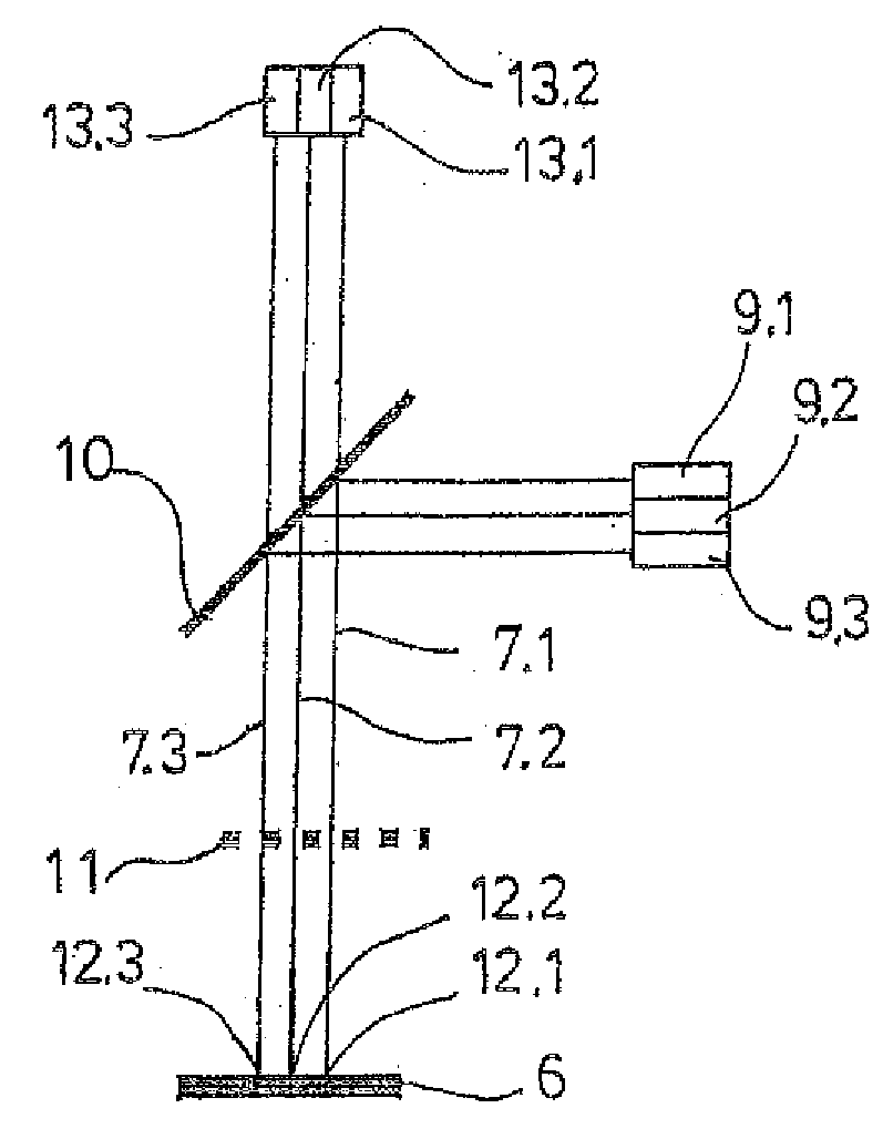
[0020]The mentioned advantageous effects are achieved in particular when the device for projecting projects the light simultaneously to plural illumination positions and / or when it projects the light to the same illumination position under different angles simultaneously and only one single photo detector is at hand. Further, they are achieved when the device for projecting illuminates only one illumination position under only one angle and plural photo detectors are at hand. They are achieved in a particularly advantageous way when the device for projecting illuminates plural illumination positions at the same time and / or when it illuminates the same illumination position simultaneously under different angles and plural photo detectors are at hand.
[0021]The optical sensor system can detect different kinds of interfaces, liquids and objects in particular, with diffusely or directedly reflecting interfaces in particular. Thus, it may be used in particular to determine the position and / or identity of interfaces or of the liquids or objects featuring the same, respectively. In principle, the device for projecting can project the light of an extraneous light source. According to one embodiment, the device for projecting has at least one light source. According to a further embodiment, the light source is at least one laser, LED or light bulb. For instance, the laser is a semiconductor laser, a laser diode in particular.
[0022]When the device for projecting has plural light sources, the light of different light sources can be projected to different illumination positions absolutely at the same time, and / or it can be projected simultaneously to the same illumination position under different angles. However, the present invention incorporates also realisations in which the light of different light sources is projected offset in time to plural illumination positions and / or is projected offset in time to the same illumination position under different angles, so that only one light source is switched on at a certain point in time. These realisations also permit a more rapid detection of the interface, in particular when the light sources are switched on in a very rapid sequence, because by doing so the interface can be scanned much more rapidly than by displacing the known one-beam sensor system by means of the adjustment device. The consecutive switching-on of plural light sources can aid in assigning the measurement signals to the different light sources. Thus, plural light sources switched on one after the other illuminate the different illumination positions quasi simultaneously or illuminate one illumination position quasi simultaneously under different angles, and therefore they are switched on simultaneously in the spirit of the invention.
[0023]According to one embodiment, the light source emits light having a wavelength which is reflected in a particularly high degree by an interface to be detected. Accordingly, light with a wavelength other than that used for the detection of the interface of an object can be used for the detection of the interface of a liquid. When it is worked with light of a wavelength for which the liquid is un-transparent, the liquid level can be acquired free of disturbances through vessel walls nearby. When the liquid is transparent for light of a certain wavelength, the location of the vessel bottom can be detected across the liquid with this light. The suitable wavelength for the detection of a liquid can depend on the composition thereof (aqueous or organic solutions, for instance). The suitable wavelength for the detection of the surface of an object can depend on from which material (metal or plastics, e.g.), with which properties (transparent, reflecting, glossy, matte and so on) the same is made. Wavelengths in a broad range come into consideration, which includes visible and invisible light (IR- and UV-radiation). Laser diodes are at hand for the range of visible light in particular.
[0024]According to one embodiment, the device for projecting has plural separately switchable light sources with different wavelengths, which can be switched on depending on the interface to be detected. According to another embodiment, the device for projecting has one light source with adjustable wavelength (a tuneable laser diode for instance).
[0025]These embodiments permit to detect an interface with light of different wavelengths. Invalid measurement values can be recognised and discarded after check-up of the measurement with light of another wavelength. In particular, when only a very small amount of liquid is contained in a vessel, it is important to discriminate between the surface of the liquid and the bottom of the vessel. When measuring with light of only one wavelength, this may be very difficult. The use of light with different wavelengths facilitates the assignment, in particular when the wavelength is optimised according to measurement case and material.

Problems solved by technology

The shapes of these interfaces are determined by gravitation, dimensions of the vessels, fill-in mode of the liquid, surface tension of the liquid, wetting properties of the walls of the vessels and further complex influences, which do not permit any prediction of the optimum reflexion site in which the illuminating device and the imaging system are aligned perpendicularly towards the interface.

Method used


Image

  • Optical sensor system on an apparatus for treating liquids.
  • Optical sensor system on an apparatus for treating liquids.
  • Optical sensor system on an apparatus for treating liquids.

Examples


Embodiment Construction

[0089]While this invention may be embodied in many different forms, there are described in detail herein a specific preferred embodiment of the invention. This description is an exemplification of the principles of the invention and is not intended to limit the invention to the particular embodiment illustrated

[0090]In the following description, coincident parts of different realisation examples are designated with the same reference numerals.

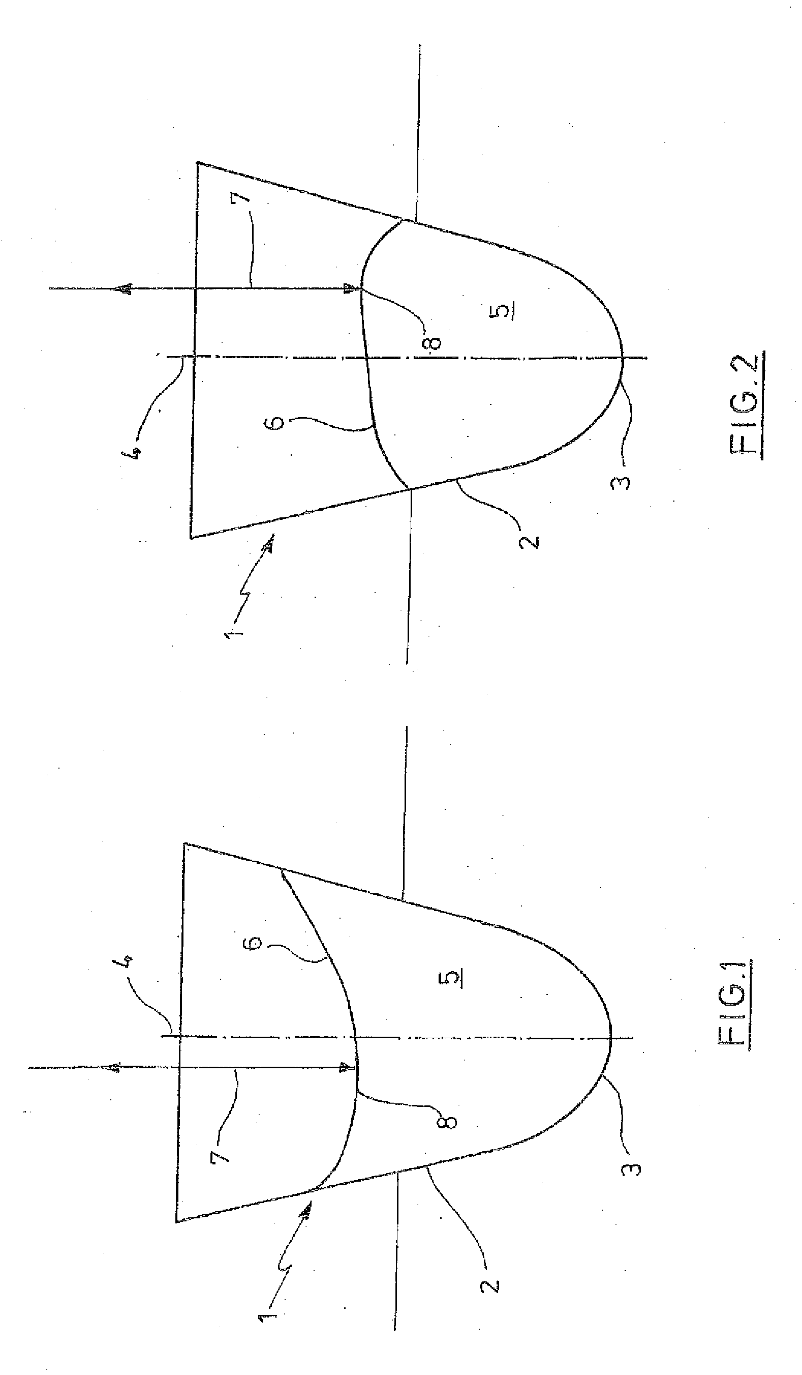
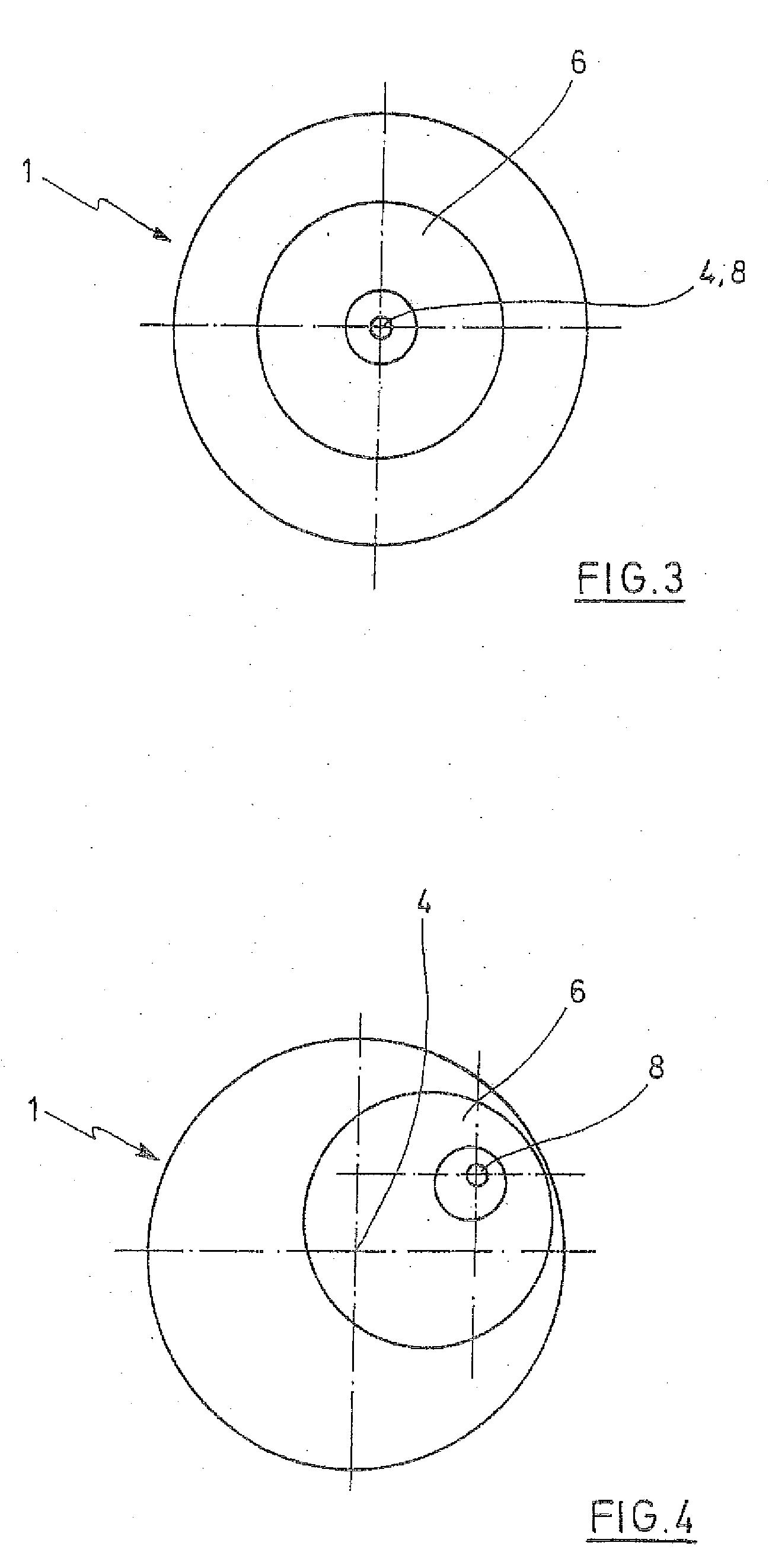
[0091]FIG. 1 to 7 show examples for the generation of the liquid level in a reaction vessel with a capacity in the range of a fraction of a millilitre up to some millilitres. Such reaction vessels are marketed by the applicant under the designation of “Eppendorf Röhrchen” or “Eppendorf tubes”, respectively.

[0092]The vessels 1 are conical in the lower part 2 and have a vessel bottom 3 concavely domed at the inside. The vessels 1 are aligned vertically with their axis 4.

[0093]According to FIG. 1, a liquid 5 arranged in the vessel 1 has a concavel...


PUM


Abstract

An optical sensor system on an apparatus for treating liquids, with a device for projecting light to at least one illumination position in space, at least one device for imaging the at least one illumination position on at least one photo detector in order to supply a measurement signal depending on the received light, wherein the device for projecting is a device for simultaneously projecting light to plural illumination positions and/or the device for projecting is a device for simultaneously projecting light under different angles to the same illumination position, and/or plural photo detectors are existent, and an analysing unit connected to the at least one photo detector for analysing the at least one measurement signal.

Description

CROSS-REFERENCE TO RELATED APPLICATIONS[0001]Not applicable.STATEMENT REGARDING FEDERALLY SPONSORED RESEARCH[0002]Not applicable.BACKGROUND OF THE INVENTION[0003]The present invention is related to an optical sensor system on an apparatus for treating liquids.[0004]An optical sensor system of the type of the present invention serves for the determination of the height of a liquid level in vessels (reaction vessels or wells of microtiter plates, for instance), of the position and the identity of vessels (reaction vessels or microtiter plates, for instance) and of the position and the identity of objects (e.g. tools, accessories, pipette points in a rack and other so-called “labware” in an apparatus for treating liquids.[0005]In particular, an apparatus for treating liquids can be an apparatus for metering and / or transporting and / or examining and / or processing (chemically, physically or biologically) liquids. In known apparatuses for treating liquids, the processes are performed eithe...

Claims


Application Information

Patent Timeline
Patent Type & Authority Applications(United States)
IPC IPC(8): G01B11/00
CPCG01F23/292G01N2035/1025G01N35/1016
Inventor GOTZ, REINHOLDHARNACK, KURTKNOFE, HELMUTKROOG, JENS-PETERSCHEFFLER, PETER
Owner EPPENDORF SE
Why Eureka
Try Eureka