
Pneumatic tire

a technology of pneumatic tires and tyres, which is applied in the direction of special tyres, vehicle components, non-skid devices, etc., to achieve the effects of reducing rolling resistance, excellent conductiveness, and easy carrying of electricity

Inactive Publication Date: 2005-03-03
SUMITOMO RUBBER IND LTD
View PDF5 Cites 12 Cited by
  • Summary
  • Abstract
  • Description
  • Claims
  • Application Information

AI Technical Summary

Benefits of technology

[0008] The present invention has been made in such a background. It is an object of the present invention to provide a tire which exhibits a high antistatic effect and reduces a rolling resistance.
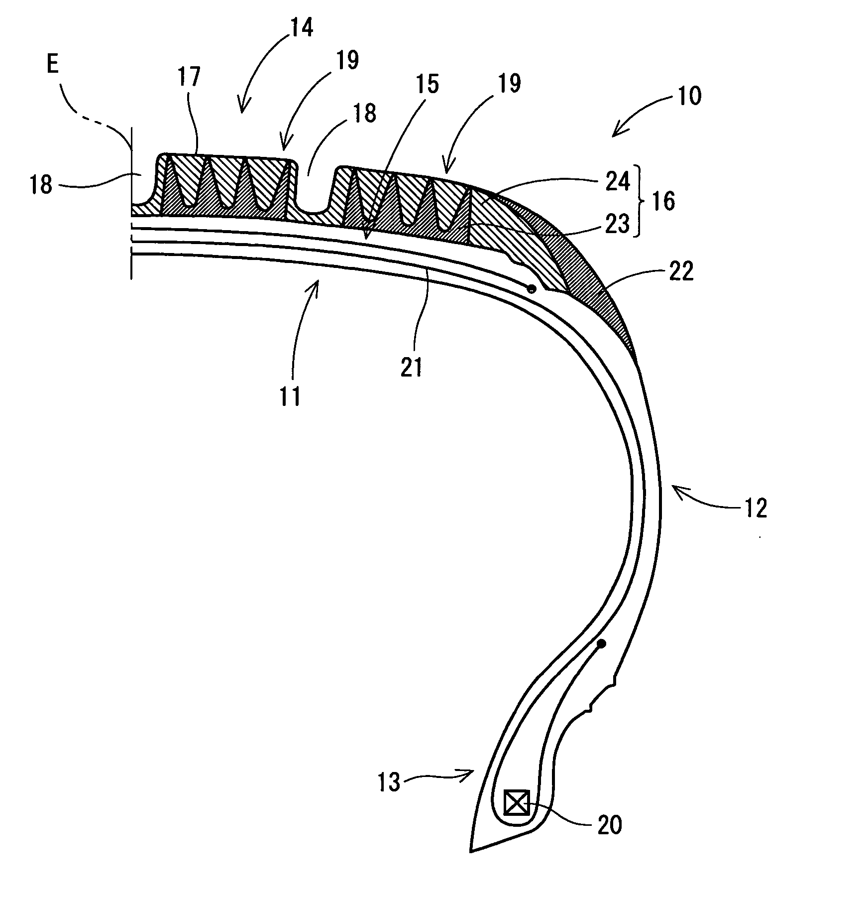
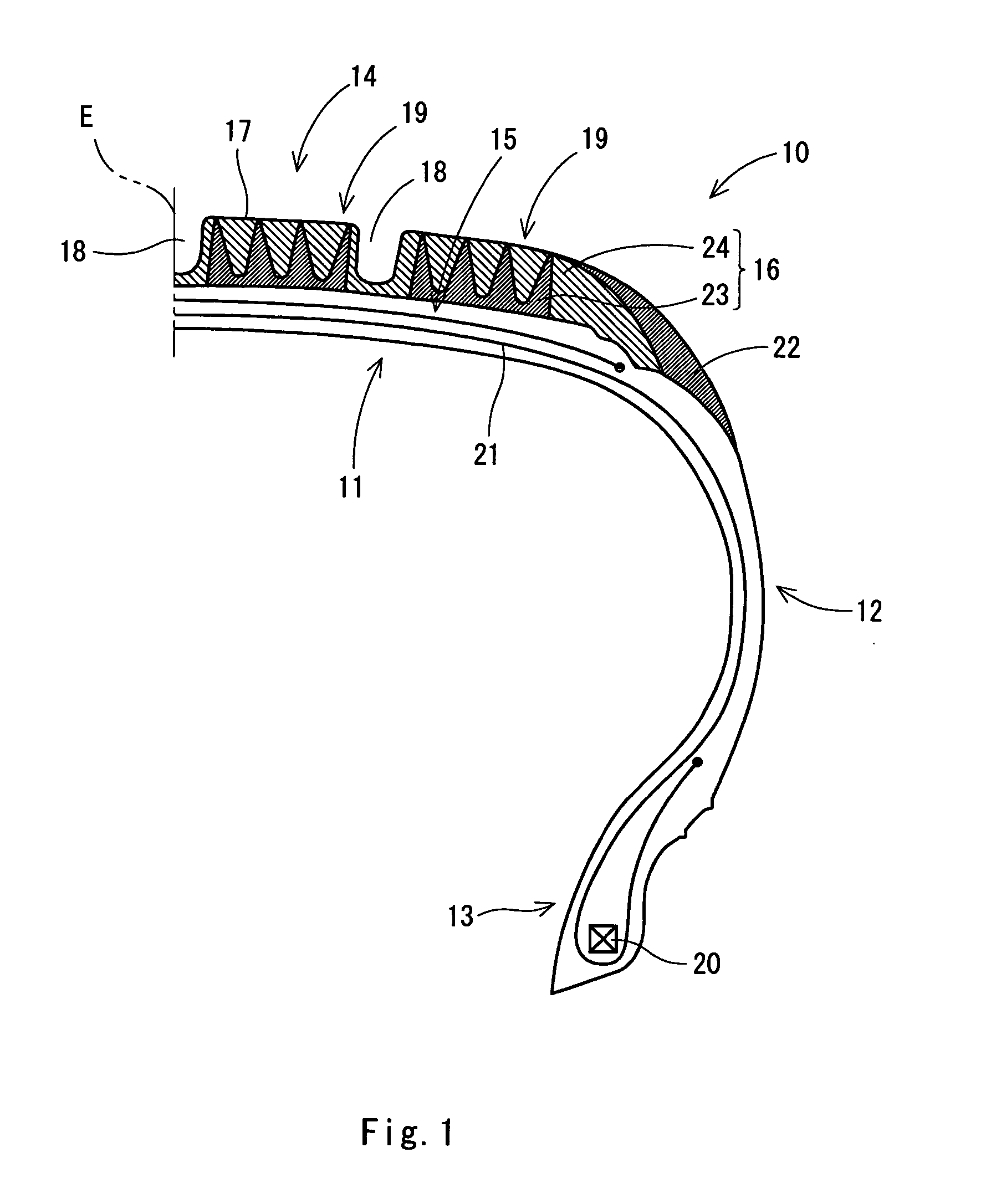
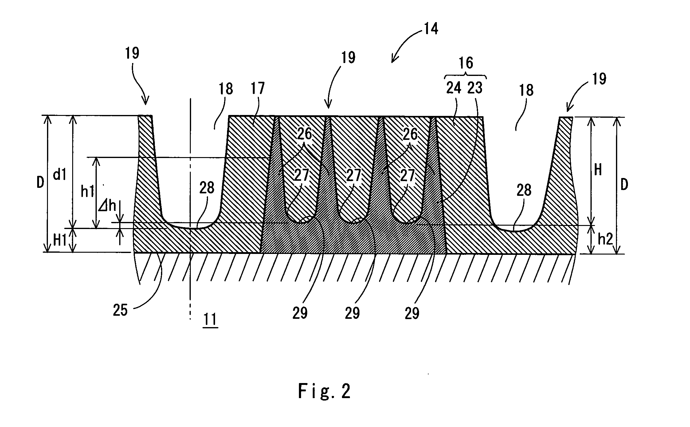
[0010] According to this structure, the tread has a two-layer structure having the base layer and the cap layer. The base layer is provided with a plurality of circular convex portions, and at least one of them is exposed to the tread surface. In other words, the circular convex portion is exposed to the tread surface of the tire in the circumferential direction. Also in the case in which a rubber constituting the cap layer is not particularly excellent in a conductiveness, therefore, electricity can easily be carried between the tire and a road surface. Accordingly, also in the case in which silica is blended with a rubber constituting the tread , for example, a conductiveness between the tire and the road surface can be maintained and a rolling resistance can be reduced.
[0011] (2) It is possible to employ such a structure that the cap layer contains silica and the base layer does not contain the silica. With this structure, the silica is blended with only the cap layer. Therefore, a wet grip performance can effectively be enhanced for only the contact portion of the tire, and furthermore, the rolling resistance can be reduced.
[0012] (3) It is desirable to employ a structure in which the grooves are provided on the outer peripheral surface so that a plurality of circular land portions is formed on the outer peripheral surface, and the circular convex portions are provided in one of the circular land portions. With this structure, the number of the circular convex portions to be exposed to the tread surface is increased. Consequently, the conductiveness can be enhanced still more.
[0013] (4) The base layer may have a hardness set to be smaller than that of the cap layer. In that case, it is preferable that the hardnesses of the base layer and the cap layer should have JIS A hardnesses set to be 55 to 65. With this structure, the wet grip performance of the tire can further be enhanced, and furthermore, the rolling resistance can further be reduced.
[0014] According to the present invention, the tread has the two-layer structure, and a plurality of circular convex portions is provided on the base layer to be an inner layer and is exposed to the tread surface. Also in the case in which the rubber constituting the cap layer is not particularly excellent in the conductiveness, therefore, a sufficient conductiveness can be maintained between the tire and the road surface. As a result, also in the case in which the silica is blended with the rubber constituting the tread, for example, the tire can exhibit a high conductiveness and can reduce the rolling resistance.

Problems solved by technology

Also in the case in which a rubber constituting the cap layer is not particularly excellent in a conductiveness, therefore, electricity can easily be carried between the tire and a road surface.

Method used


Image

  • Pneumatic tire
  • Pneumatic tire
  • Pneumatic tire

Examples


example 1

[0046] For a cap layer, a ratio to a tread rubber layer is 80% and a rubber hardness (JIS A hardness) is 64. Moreover, the composition of a rubber constituting the cap layer is of a blend I type and a predetermined amount of silica is blended. On the other hand, for a base layer, the ratio to the tread rubber layer is 20% and the rubber hardness is 60. The number of convex portions is two and the number of the exposed convex portions to a tread surface is two. Furthermore, the composition of a rubber constituting the base layer is of a blend II type, and the silica is not blended but carbon black is blended at a relatively high rate.

example 2

[0047] For a cap layer, a ratio to a tread rubber layer is 80% and a rubber hardness (JIS A hardness) is 64. Moreover, the composition of a rubber constituting the cap layer is of a blend I type and a predetermined amount of silica is blended. On the other hand, for a base layer, the ratio to the tread rubber layer is 20% and the rubber hardness is 59. The number of convex portions is two and the number of the exposed convex portions to a tread surface is two. Furthermore, the composition of a rubber constituting the base layer is of a blend III type, and the silica is not blended but carbon black is blended at a relatively low rate.

example 3

[0048] For a cap layer, a ratio to a tread rubber layer is 80% and a rubber hardness (JIS A hardness) is 64. Moreover, the composition of a rubber constituting the cap layer is of a blend I type and a predetermined amount of silica is blended. On the other hand, for a base layer, the ratio to the tread rubber layer is 20% and the rubber hardness is 59. The number of convex portions is six and the number of the exposed convex portions to a tread surface is two. Furthermore, the composition of a rubber constituting the base layer is of a blend III type, and the silica is not blended but carbon black is blended at a relatively low rate.


PUM


Abstract

A tread (14) of a tire (10) includes a tread rubber layer (16). The tread rubber layer (16) has a two-layer structure including a base layer (23) and a cap layer (24). The base layer (23) is provided with a comb-shaped convex portion (26). The convex portion (26) is formed like a circle extended in the circumferential direction of the tire (10). A plurality of convex portions (26) is arranged in the axial direction of the tire (10) and is protruded in a radial direction. At least a part of the convex portions (26) is exposed to a tread surface (17) when the tire (10) is unused (brand-new). The cap layer (24) contains silica and the base layer (23) does not contain the silica.

Description

[0001] This application claims priority on Patent Application No. 2003-310962 filed in Japan on Sep. 3, 2003. BACKGROUND OF THE INVENTION [0002] 1. Field of the Invention [0003] The present invention relates to a structure of a pneumatic tire (hereinafter referred to as a “tire”). [0004] 2. Description of the Related Art [0005] A portion to come in contact with the road surface of a tire is particularly referred to as a tread. The tread has a tread rubber layer. The physical properties of a rubber constituting the tread rubber layer directly influence the performance of the tire. Conventionally, importance has been particularly attached to a wet grip performance and a rolling resistance in the performance of the tire. In the case in which the wet grip performance is enhanced, however, the rolling resistance generally tends to be increased. For this reason, the tire has conventionally been improved to suppress a rise in the rolling resistance with an enhancement in the wet grip perfo...

Claims


Application Information

Patent Timeline
Patent Type & Authority Applications(United States)
IPC IPC(8): B60C11/00B60C11/04B60C11/18B60C19/08
CPCB60C11/00B60C19/08B60C11/005B60C11/0058Y10S152/02
Inventor SUZUKI, KAZUYA
Owner SUMITOMO RUBBER IND LTD
Learn More