Method and apparatus for kidney dialysis

Inactive Publication Date: 2005-03-03
CONNELL MARK E +9
View PDF3 Cites 209 Cited by
  • Summary
  • Abstract
  • Description
  • Claims
  • Application Information

AI Technical Summary

Problems solved by technology

While machines according to the prior art provide a number of a

Method used


Image

  • Method and apparatus for kidney dialysis
  • Method and apparatus for kidney dialysis
  • Method and apparatus for kidney dialysis

Examples


Embodiment Construction

Hydraulic Circuit

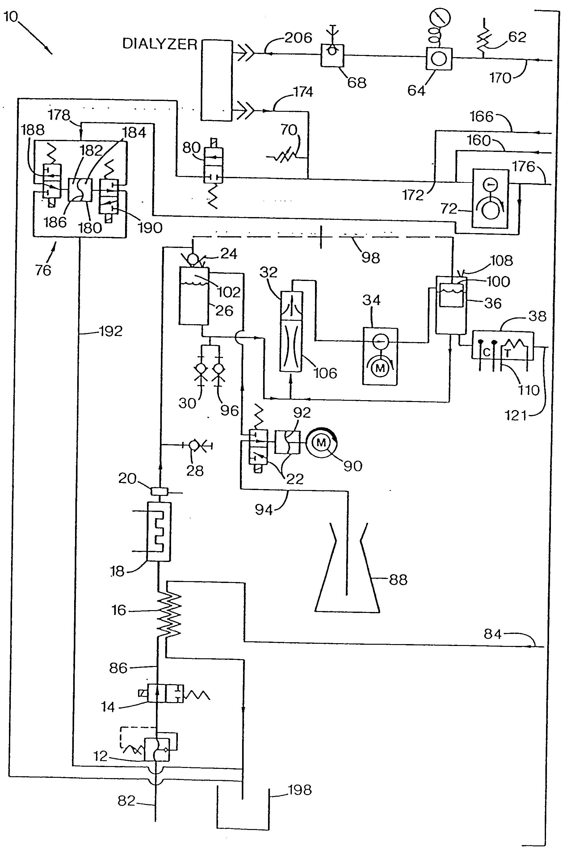
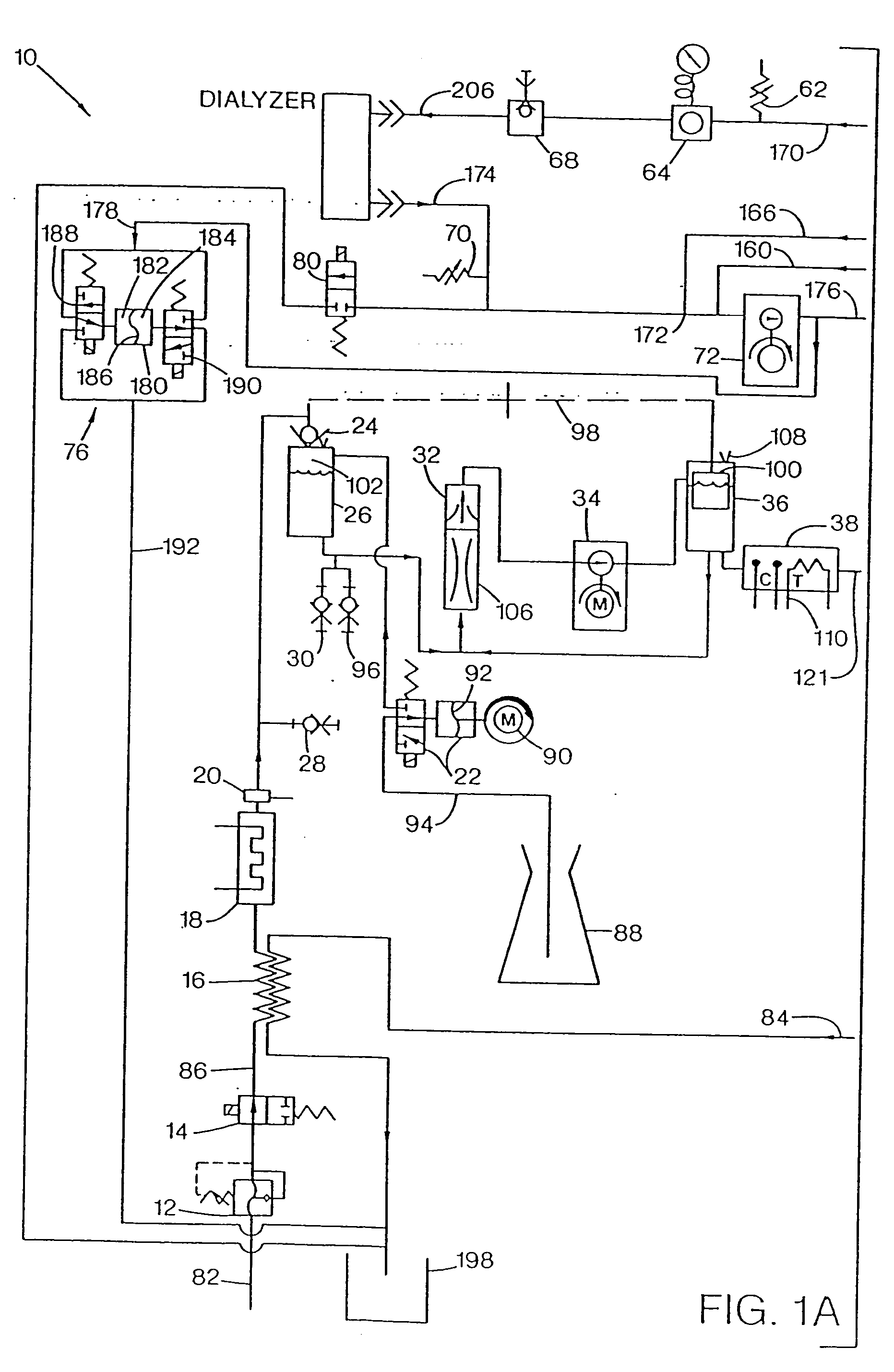
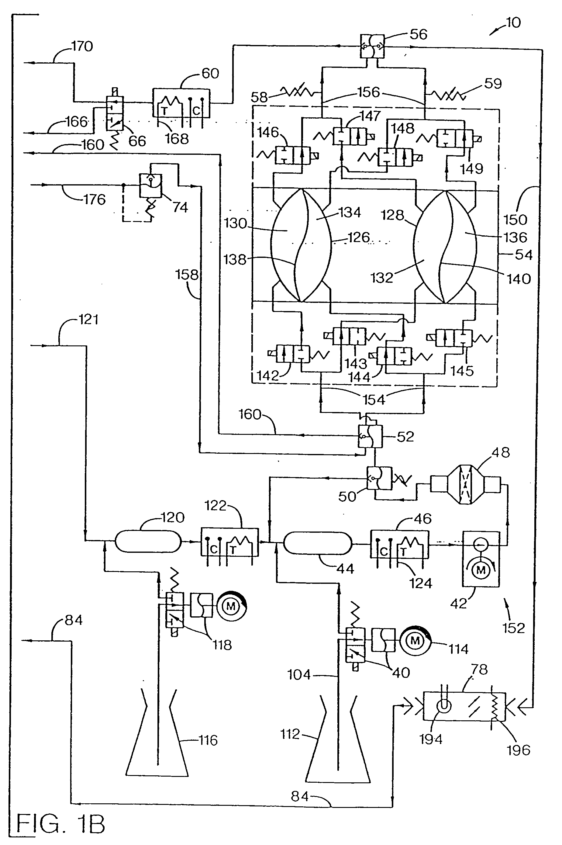
A hydraulic circuit 10 representing a preferred embodiment of an improved hemodialysis machine according to the present invention is illustrated in FIG. 1. The hydraulic circuit 10 is comprised of the following principal components: an incoming water pressure regulator 12, a water on / off valve 14, a heat exchanger 16, a heater 18, a safety thermostat 20, an “A” concentrate pump 22, a supply valve 24, an air gap chamber 26, an “A” rinse fitting 28, a “B” rinse fitting 30, a deaeration sprayer 32, an air removal pump 34, a vented air trap 36, an “A” conductivity probe 38, a “B” concentrate pump 40, a supply pump 42, a “B” mix chamber 44, a “B” conductivity probe 46, a dialysate filter 48, a supply regulator 50, an input pressure equalizer 52, a flow equalizer 54, an output pressure equalizer 56, end-of-stroke sensors 59, a dialysate conductivity probe 60, a pre-dialyzer flow sensor 62, a dialysate pressure transducer 64, a bypass valve 66, a dialysate sample port 68...


PUM

PropertyMeasurementUnit
Timeaaaaaaaaaa

Abstract

A number of improvements relating to methods and apparatuses for kidney dialysis are disclosed. These include checking of dialysate bypass status using flow measurement; using a flow sensor to confirm the absence of ultrafiltration during bypass; automatic testing of ultrafiltration function by removal of a discrete volume from a portion of the dialysate flow path coupled with a pressure test of that part of the flow path; using a touch screen user interface; bar graph profile programming of ultrafiltration, sodium, and bicarbonate parameters; using a RAM card to upload treatment instructions to, and to download treatment data from, the machine; automatic setting of proportioning mode (acetate or bicarbonate) based on connections of concentrate lines; predicting dialysate conductivity values based on brand and formulation of concentrates; minimizing no-flow dead time between dialysate pulses; initiating operation in a timed mode from a machine power-off condition; preserving machine mode during machine power-fail condition; calibration scheduling and reminding; automatic level adjusting; and blood leak flow rate detecting.

Description

FIELD OF THE INVENTION The present invention relates to improvements in kidney dialysis machines. BACKGROUND OF THE INVENTION Kidney dialysis machines are well known in the art and are illustrated, for example, in U.S. Pat. Nos. 3,598,727, 4,172,033, 4,267,040, and 4,769,134. While machines according to the prior art provide a number of advantageous features, they nonetheless have certain limitations. The present invention seeks to overcome certain drawbacks of the prior art and to provide new features not heretofore available. A discussion of the features and advantages of the present invention is deferred to the following detailed description, which proceeds with reference to the accompanying drawings.BRIEF DESCRIPTION OF THE DRAWINGS FIG. 1 is a schematic hydraulic diagram of a preferred embodiment of a kidney dialysis machine according to the present invention. FIG. 2 is a schematic diagram showing flow path locations and components of a pre-dialyzer flow sensor and a post-d...

Claims


Application Information

Patent Timeline
IPC IPC(8): A61M1/16A61M1/36A61M39/10B01D61/32G06F3/033G06F3/048
CPCA61M1/16A61M1/1613A61M1/168A61M1/1692A61M1/1694A61M1/3626A61M2039/1005A61M2205/505A61M2205/52G06F3/0482G06F3/04847G06Q50/22Y10S210/929A61M1/1607A61M1/165A61M1/1656A61M1/1686A61M1/169A61M2205/3313A61M2205/3317A61M2205/3324A61M2205/3334A61M2205/3368A61M1/1664A61M1/1666A61M1/1684A61M1/1688A61M1/341G16H40/63G16H20/40
Inventor CONNELL, MARK E.BEDIENT, ROBERT A.ELSEN, RAYMONDHOGARD, MICHAEL E.JOHNSON, HARLEY D.KELLY, THOMAS D.LONG, JEAN MCEVOYPETERSON, BRUCE A.PRESTON, WILLIAM G. JR.SMEJTEK, DALIBOR J.
Owner CONNELL MARK E
Why Eureka
Try Eureka