Dynamic logic register

a register function and dynamic logic technology, applied in the field of dynamic logic and register functions, can solve problems such as significant slow operation speed, and achieve the effect of preventing data signal perturbation

Active Publication Date: 2005-03-03
VIA TECH INC
View PDF17 Cites 50 Cited by
  • Summary
  • Abstract
  • Description
  • Claims
  • Application Information

AI Technical Summary

Benefits of technology

[0009] A dynamic logic register according to an embodiment of the present invention includes a complementary pair of evaluation devices, delayed inversion logic, a dynamic evaluator, latching logic, and a keeper circuit. The complementary pair of evaluation devices is responsive to a clock signal and provides a pre-charged node and an evaluation node. The delayed inversion logic receives the clock signal and outputs a complete signal that is a delayed and inverted version of the clock signal. The dynamic evaluator is coupled between the pre-charged and evaluation nodes and evaluates a logic function based on at least one inp...

Problems solved by technology

Preceding and following a logical evaluation circuit with traditional register circuits introduces delays into a pipeline system whose cumulative effect results in significantly slower opera...

Method used


Image

  • Dynamic logic register
  • Dynamic logic register
  • Dynamic logic register

Examples


Embodiment Construction

[0022] The following description is presented to enable one of ordinary skill in the art to make and use the present invention as provided within the context of a particular application and its requirements. Various modifications to the preferred embodiment will, however, be apparent to one skilled in the art, and the general principles defined herein may be applied to other embodiments. Therefore, the present invention is not intended to be limited to the particular embodiments shown and described herein, but is to be accorded the widest scope consistent with the principles and novel features herein disclosed.

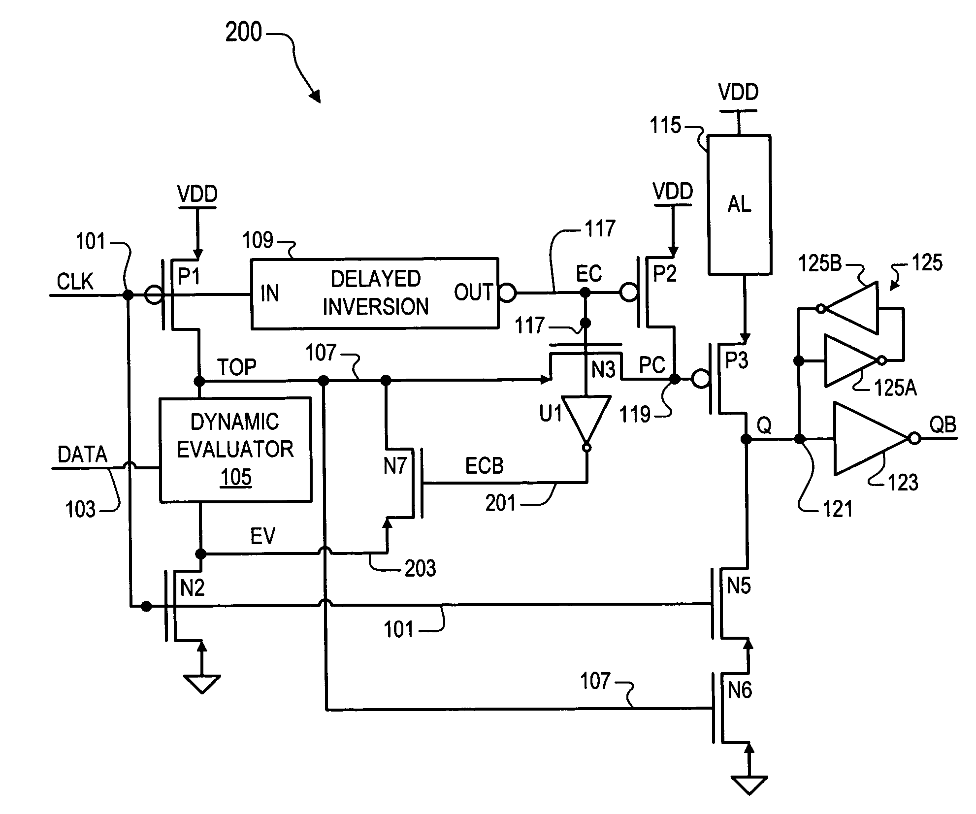
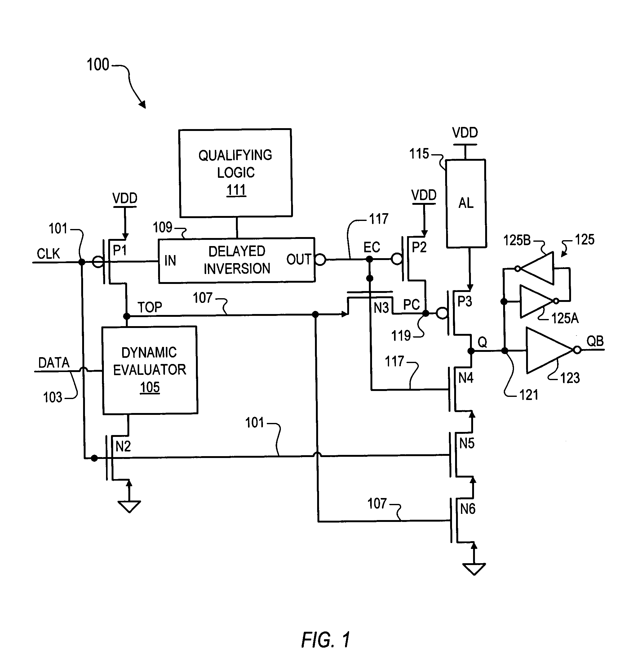
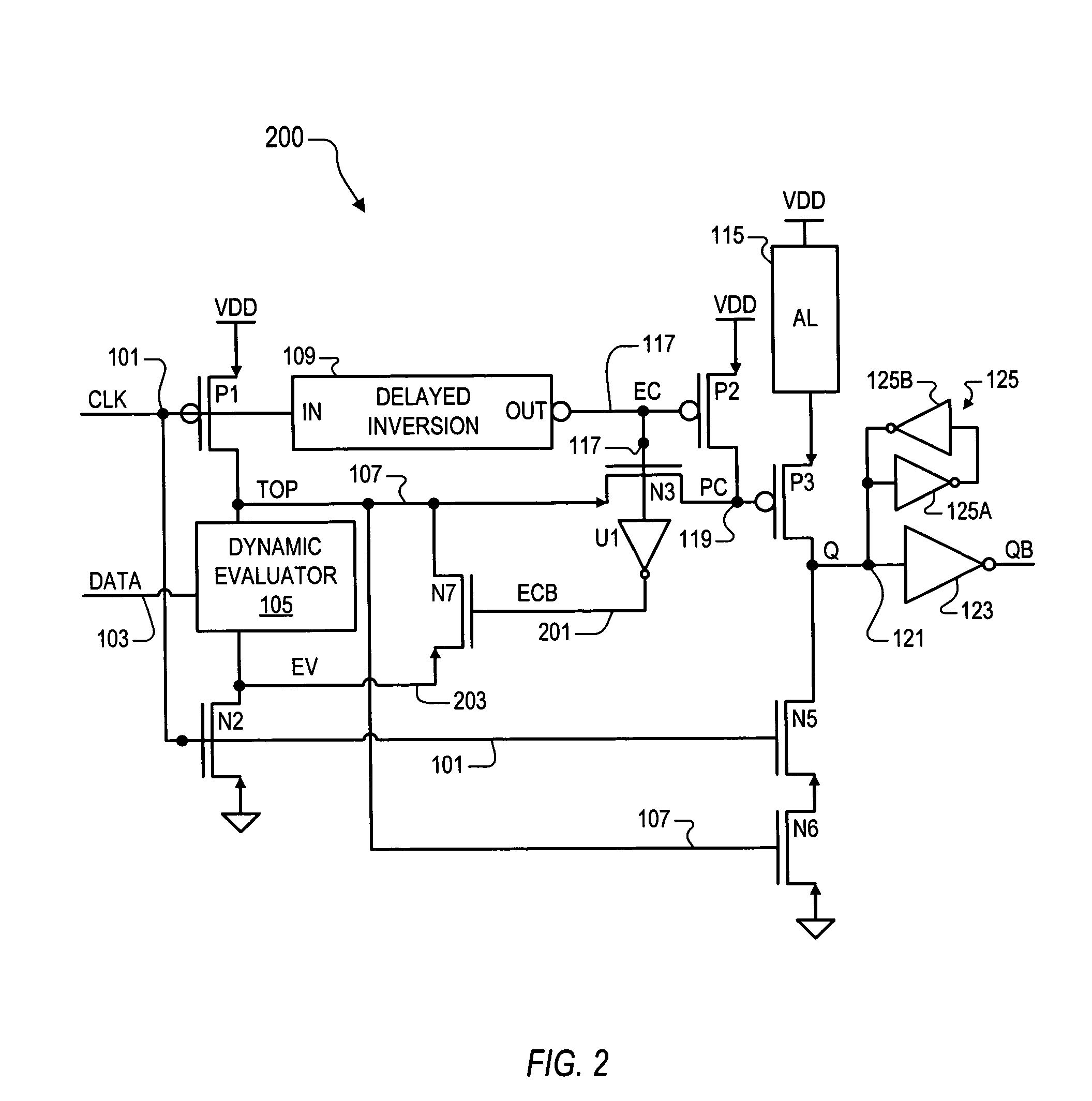
[0023] The inventors of the present application have recognized the need for providing registered outputs for logic circuits in which speed is a critical factor and also for optimizing the overall design such as by reducing the number of devices to increase speed and reduce chip area consumed. They have therefore developed a dynamic logic register that provides latched inputs...


PUM


Abstract

A dynamic logic register including a complementary pair of evaluation devices, delayed inversion logic, a dynamic evaluator, latching logic, and a keeper circuit coupled to the output. The evaluation devices are responsive to a clock signal and provide a pre-charged node and an evaluation node. The delayed inversion logic outputs a complete signal that is a delayed and inverted version of the clock signal. The dynamic evaluator, coupled between the pre-charged and evaluation nodes, evaluates a logic function based on a data signal during an evaluation period between operative edges of the clock and complete signals. The latching logic enables the state of an output node to be determined by the state of the pre-charged node during the evaluation period and otherwise clamps the pre-charged node to prevent perturbations of the data signal from propagating to the output node.

Description

CROSS-REFERENCE TO RELATED APPLICATIONS [0001] This application claims the benefit of U.S. Provisional Application Ser. No. 60 / 498187, filed on 8 / 27 / 2003, which is herein incorporated by reference for all intents and purposes. [0002] This application is a continuation-in-part of the following co-pending U.S. pat. application, which has a common assignee and at least one common inventor, and which is herein incorporated by reference in its entirety for all intents and purposes: FILINGSER. NO.DATETITLE10 / 730703Dec. 5, 2003DYNAMIC LOGIC REGISTER(CNTR.2196)BACKGROUND OF THE INVENTION [0003] 1. FIELD OF THE INVENTION [0004] The present invention relates to dynamic logic and register functions, and more particularly to a dynamic logic register that provides registered outputs for logic evaluation functions. [0005] 2. DESCRIPTION OF THE RELATED ART [0006] Integrated circuits use a remarkable number of registers, particularly those having a synchronous pipeline architecture. Register logic...

Claims


Application Information

Patent Timeline
IPC IPC(8): G11C19/00G11C19/28
CPCG11C19/28G11C19/00
Inventor QURESHI, IMRANLUNDBERG, JAMES R.
Owner VIA TECH INC
Why Eureka
Try Eureka