Fibre channel interface unit

Inactive Publication Date: 2005-03-03
THE BOEING CO
View PDF8 Cites 7 Cited by
  • Summary
  • Abstract
  • Description
  • Claims
  • Application Information

AI Technical Summary

Benefits of technology

[0012] The present invention provides a Fibre Channel interface apparatus and methods that are able to monitor multiple nodes of a Fibre Channel network, extract node specific information, and communicate the information to conventional recorders. Advantageously, the present invention does not entail use of prior knowledge of upper level protocol layers and is independent of protocols. As a result, complex protocol programming is avoided. As a further result, the present invention may be quickly and easily installed into any Fibre Channel networked system.

Problems solved by technology

With multiple switches, multiple paths can be found and, therefore, variable frame delays may result.
This may cause a next frame in a sequence to be routed using another path, which can create different delays for each frame of a sequence.
Therefore, use of multiple switches to provide redundancy complicates even further the task of monitoring of communications within a Fibre Channel network including multiple switches.
Also, communications that may be monitored may be limited to those that comply with certain upper level communication protocols.
As a result, such monitoring may be time and labor intensive, expensive, and limited in applicability.

Method used


Image

  • Fibre channel interface unit
  • Fibre channel interface unit
  • Fibre channel interface unit

Examples


Embodiment Construction

[0027] The present invention relates to Fibre Channel interface apparatus and methods. Many specific details of certain embodiments of the invention are set forth in the following description and in FIGS. 4-8 to provide a thorough understanding of such embodiments. One skilled in the art, however, will understand that the present invention may have additional embodiments, or that the present invention may be practiced without several of the details described in the following description.

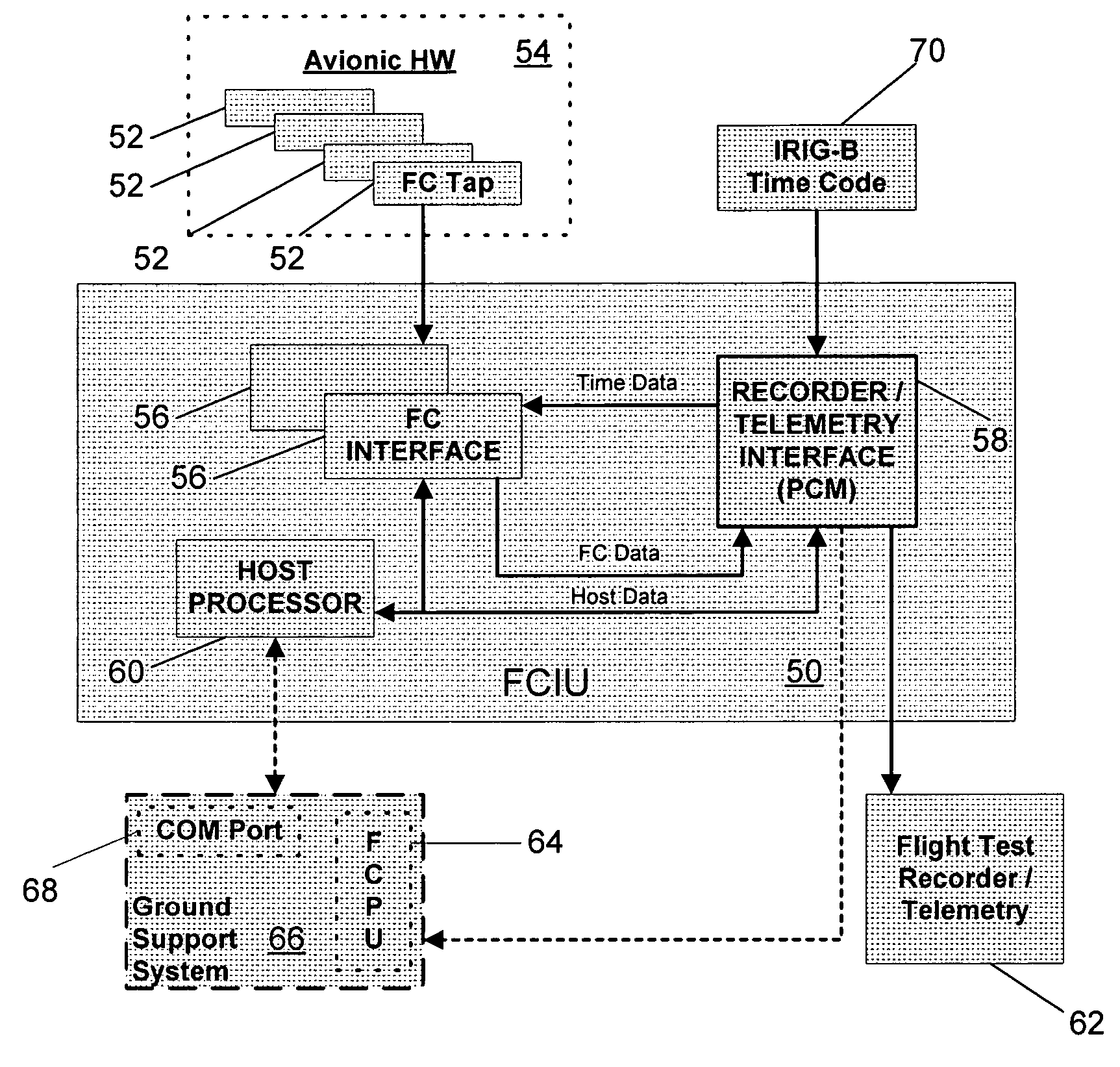
[0028] By way of overview, in one embodiment in accordance with the present invention, a device is provided for interfacing with at least one node in a Fibre Channel network. The device includes at least one input interface that is couplable to receive a plurality of frames of data that are transmitted from or received at a node of the Fibre Channel network. An output telemetry interface is couplable to provide the received frames of data to a telemetry device.

[0029] Referring now to FIG. 4, an exe...


PUM


Abstract

Fibre Channel interface apparatus and methods are disclosed. In one embodiment, a system is provided for interfacing with at least one node in a Fibre Channel network. The system includes at least one input interface that is couplable to receive a plurality of frames of data that are transmitted from or received at a node of the Fibre Channel network. An output telemetry interface is couplable to provide the received frames of data to a telemetry and / or recording device.

Description

FIELD OF THE INVENTION [0001] The present invention relates generally to network interfaces and, specifically, to Fibre Channel network interfaces. BACKGROUND OF THE INVENTION [0002] In many applications, electronic equipment is interconnected and communicates with each other via a network. An example of electronic equipment interconnected in a network includes avionics, such as a radar system, on an aircraft. In order for the electronic equipment to communicate with each other, communication standards or protocol are used. One such communication standard is MIL-STD-1553. [0003] Referring to FIG. 1, a network 10 known in the prior art uses MIL-STD-1553 communications. Remote terminals, A, B, C, X, Y, and Z are coupled to a primary bus 12 and a secondary bus 14. The primary and secondary buses 12 and 14 are controlled by a bus controller 16. Because it is often desirable to monitor data that is communicated within the network 10 in order to evaluate operation of the system, a monitor...

Claims


Application Information

Patent Timeline
IPC IPC(8): H04J9/00H04L5/22H04L12/26H04L12/433
CPCH04L12/2602H04L43/00H04L12/433
Inventor ZETTWOCH, ROBERT NEAL
Owner THE BOEING CO
Why Eureka
Try Eureka