
Modular connections in a DMFC array

Inactive Publication Date: 2005-03-03
MTI MICROFUEL CELLS
View PDF11 Cites 24 Cited by
  • Summary
  • Abstract
  • Description
  • Claims
  • Application Information

AI Technical Summary

Benefits of technology

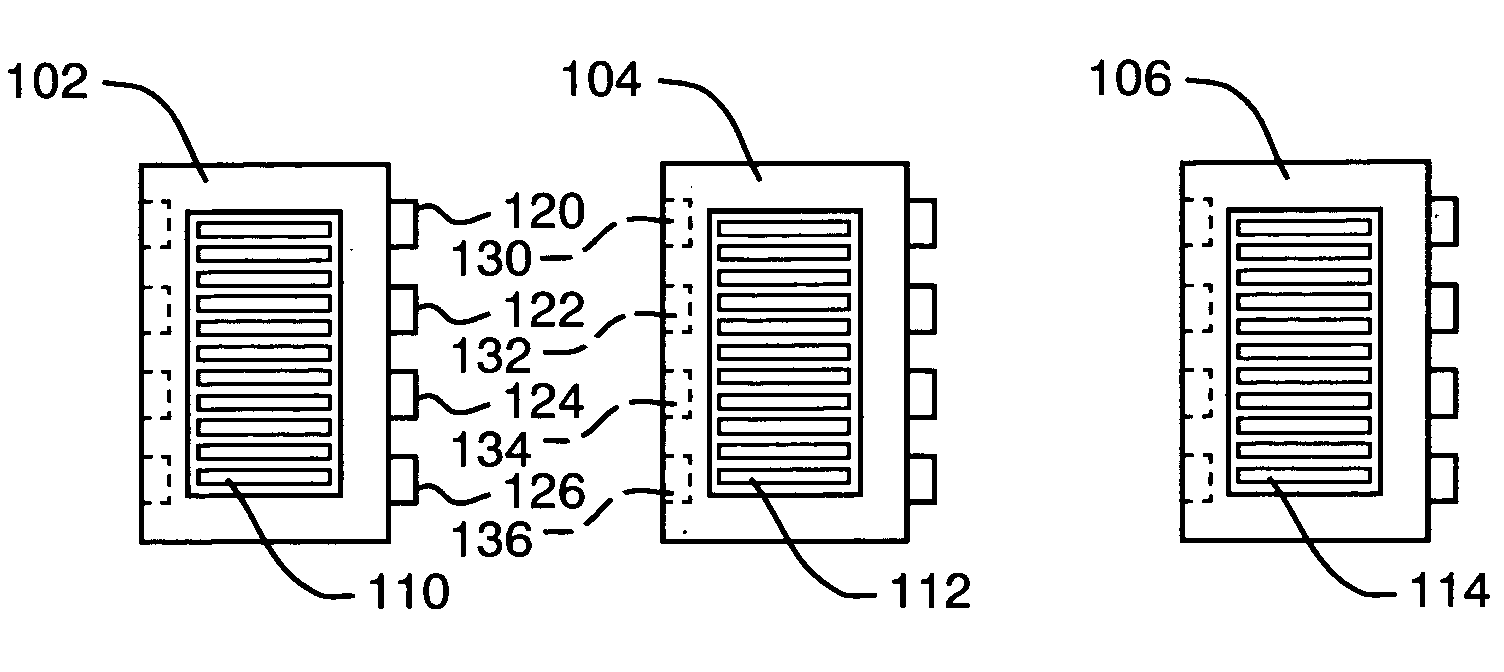
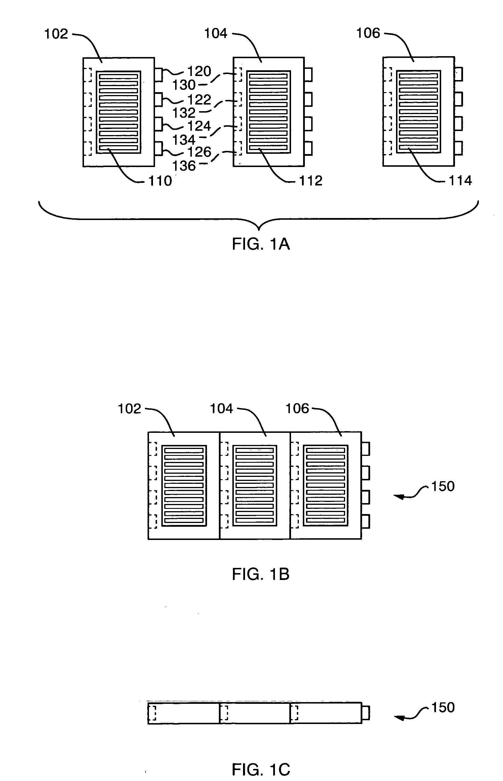
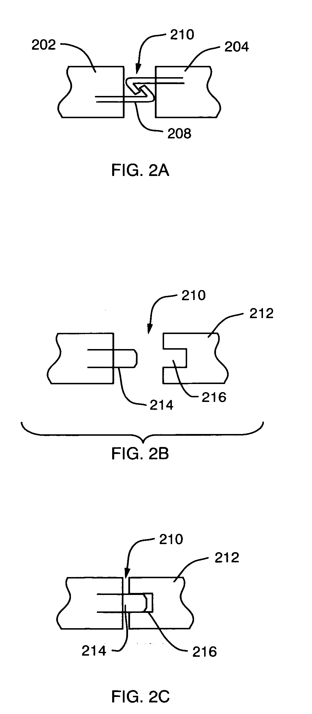
[0018] These disadvantages are overcome by the present invention, which is a modular DMFC array and a related method of manufacturing such an array. The modular DMFC array incorporates separately manufactured individual fuel cells that are connected after the manufacturing process. Components that form the electrical connections between cells are incorporated into each cell and the electrical connections are made after the cells are manufactured. This prevents the connections from being affected during the fuel cell manufacturing process. It also allows the connections to be tested easily and individually, thus improving confidence in the quality of the electrical connections. Failed cells can be identified immediately and are not incorporated into the array. Alternatively, failed cells in an array can be replaced if post-assembly testing proves that the cell is inoperative.
[0019] Another feature of the modular DMFC array of the present invention is the ability to readily change the size and capacity of an array by simply adding or removing one or more cells. This allows for flexibility in design and testing and the ability to use the same design for several applications.

Problems solved by technology

However, because fuel processing is complex, and requires expensive components, which occupy comparatively significant volume, the use of reformer based systems is presently limited to comparatively large, high power applications.
The overall reaction may be limited by the failure of either of these reactions to proceed at an acceptable rate (more specifically, slow oxidation of the fuel mixture will limit the cathodic generation of water, and vice versa).
Particular challenges arise with respect to the successful manufacture of a fuel cell array, such as manufacturing such an array with efficiency and consistent high quality.
Despite these conveniences, however, there are disadvantages associated with the single unit manufacturing process.
For example, as noted above, the cell-to-cell electrical connections can be incorporated directly into the manufacturing process, but this makes it difficult to check the connections after the array is finished, particularly in the case of a injection molded cell because the cell-to-cell connections are located within a single plastic frame created around the fuel cells.
If there is a short circuit or a broken connection, for example, or if one or more cells in the array fail to perform, the entire array fails.
The single MEA platform can also present challenges because of the sensitive nature of the materials and challenges of fabrication, causing a higher failure rate than is desirable.
And, if the array MEA fails quality control inspection, then six times the material is wasted compared with wasting one failed single cell MEA.
In other words, a single failed cell in an array that is fabricated as single component could result in an entire failed array that, in turn, leads to wasted materials.
As is known to those skilled in the art, these materials may be comparatively expensive and material yield must be maximized in a commercial manufacturing process.
Another challenge in production of a membrane electrode assembly in an array configuration is that of dimensional consistency of the materials.

Method used


Image

  • Modular connections in a DMFC array
  • Modular connections in a DMFC array
  • Modular connections in a DMFC array

Examples


embodiment

[0061] Carrier Embodiment

[0062] As noted herein above, another category of modular DMFC arrays incorporates individual fuel cells that fit in or attach to a type of underlying carrier component that provides structural stability and / or electrical conductivity. The carrier can be a rigid plate, such as an appropriate plastic or fiberglass plate, or it may be a pliable material, such as a fabric or non-woven material. Though illustrated herein as being planar, a rigid carrier component may take any number of shapes as is necessary or desirable for a particular application including, but not limited to a curvilinear form. By way of background, FIG. 5A illustrates an individual fuel cell 500 that is one building block of an array such as the array 550 of FIG. 5B. The array 550 of FIG. 5B includes the fuel cells 504 through 508. The fuel cells 504 through 508 are attached to a carrier component 560. Multiple cells in the carrier 560 are illustrated in FIG. 5C. In order to attach the fuel...


PUM


Abstract

A modular DMFC array, and a related method of manufacturing such an array is provided. The modular DMFC array incorporates separately manufactured individual fuel cells that are connected after the manufacturing process. A locking mechanism incorporates the necessary electric connections. In one embodiment of the invention, the electrical connections also function as the locking mechanism. In such an embodiment, a separate mechanical fastening mechanism is not needed. In other embodiments of the invention, mechanical connections are provided to connect the individual fuel cells in the modular fuel cell array. Yet a further embodiment includes a carrier component on which the individual fuel cells are bonded. The electrical connections are provided either through the carrier component, or cell-to-cell.

Description

CROSS-REFERENCE TO RELATED APPLICATION [0001] The present application is a continuation-in-part of commonly assigned copending U.S. patent application Ser. No. 10 / 650,424, which was filed on Aug. 28, 2003, by Megan A. Fannon et al. for a METHOD OF MANUFACTURING A FUEL CELL ARRAY AND A RELATED ARRAY and is hereby incorporated by reference.BACKGROUND OF THE INVENTION [0002] 1. Field of the Invention [0003] This invention relates generally to fuel cells, and more particularly, to the manufacture of arrays of such fuel cells. [0004] 2. Background Information [0005] Fuel cells are devices in which electrochemical reactions are used to generate electricity. A variety of materials may be suited for use as a fuel depending upon nature of the fuel cell. Organic materials, such as methanol or natural gas, are attractive fuel choices due to their high specific energy. [0006] Fuel cell systems may be divided into “reformer-based” systems (i.e., those in which the fuel is processed in some fashi...

Claims


Application Information

Patent Timeline
IPC IPC(8): H01M2/20H01M8/02H01M8/10H01M8/24
CPCH01M8/0206H01M8/0247H01M8/0269H01M8/0297H01M8/1009H01M8/1011Y02B90/18H01M8/2465H01M8/2475H01M8/249H01M2250/30Y02E60/523H01M8/2455Y02B90/10Y02E60/50Y02P70/50H01M8/2404
Inventor FANNON, MEGAN A.HIRSCH, ROBERT S.BECERRA, JUAN J.
Owner MTI MICROFUEL CELLS
Learn More