
Medical device
- Summary
- Abstract
- Description
- Claims
- Application Information
AI Technical Summary
Benefits of technology
Problems solved by technology
Method used
Image

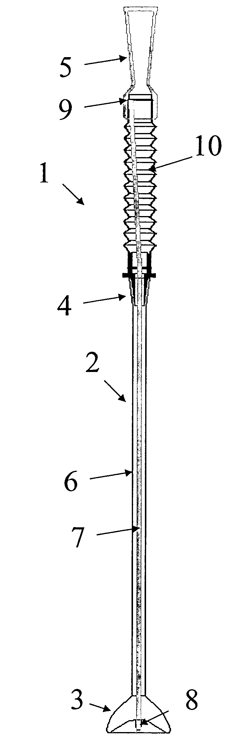
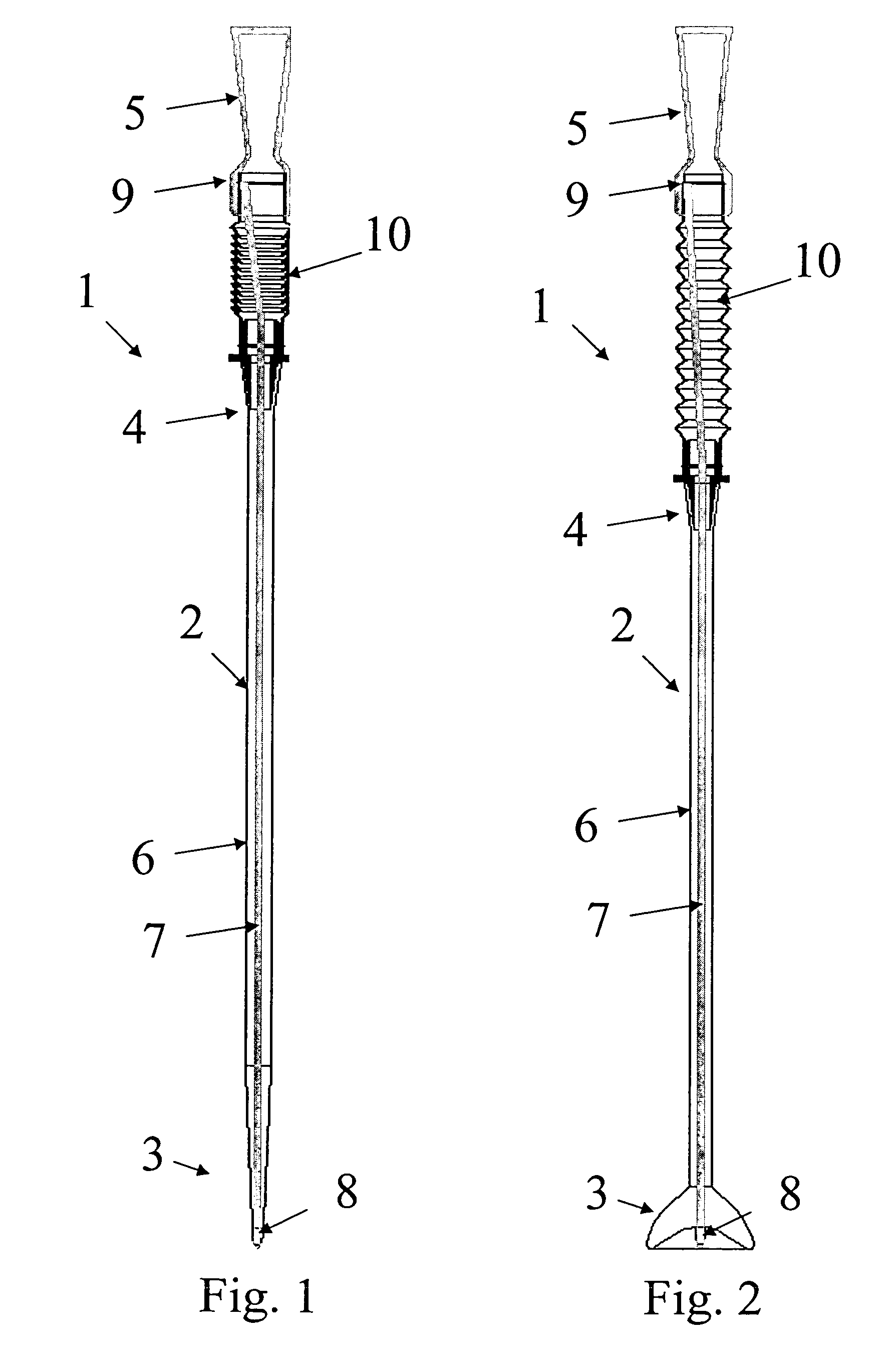
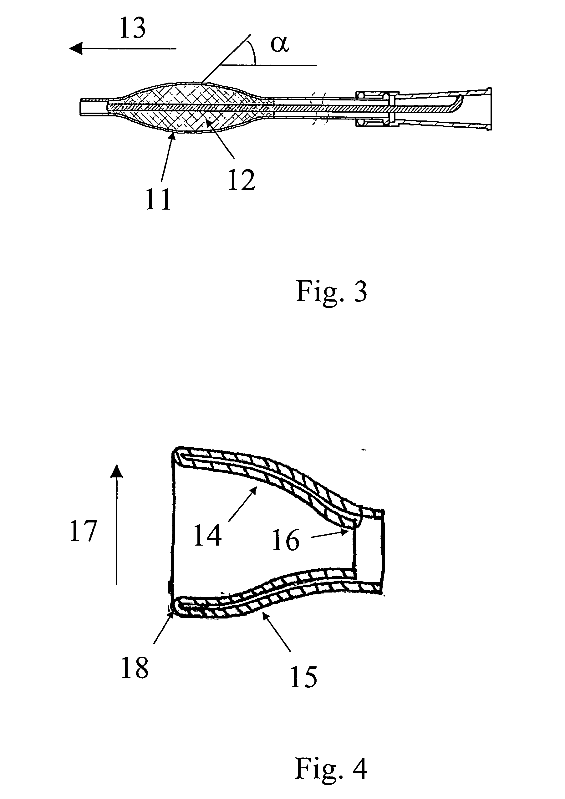
Examples
first embodiment
The medical device, especially the retention section, may be designed with “shape-memory” such that it will automatically move towards a predetermined shape i.e. towards a relaxed state. In a first embodiment the medical device is designed such that the predetermined shape is the first configuration, i.e. the medical device will have a tendency to move towards the first configuration, but may be moved into the second configuration by axial displacement of the first part of the braided portion into a second part of the braided portion. In some embodiments the first configuration is a configuration wherein the largest dimension of a cross-section of the braided portion is equal or less than the largest dimension of a cross-section of the remaining part of the tube.
second embodiment
In a second embodiment the medical device is designed such that the predetermined shape is the second configuration, i.e. the medical device will have a tendency to move towards the second configuration, but may be moved into the first configuration by axial displacement of the first part of the braided portion out of the second part of the braided portion. In some embodiments the second configuration is a configuration wherein the largest dimension of a cross-section of the braided portion is larger than the largest dimension of a cross-section of the remaining part of the tube.
third embodiment
In a third embodiment the medical device is designed such that the predetermined shape when the braided portion is located inside the remaining part of the tube, e.g. the drainage section, coaxially therewith. When the medical device is located in the body, the second part is displaced out of the remaining part of the medical device to form a medical device in the second configuration, i.e. retained in the body. To operate the medical device between the different configurations, a deployment member could be fastened in the proximal end, e.g. to a proximal tip of the medical device, and extend to the distal end to facilitate manipulation of the proximal end from outside the body. The Deployment rod could e.g. extend inside the lumen. The tip could be shaped as a Nelaton tip or as a Tiemann tip, or the tip could have the form of an open ring, e.g. with a smoothly rounded part extending in a forward direction to form a proximal end of the device and thus to facilitate comfortable inser...
PUM
| Property | Measurement | Unit |
|---|---|---|
| Angle | aaaaa | aaaaa |
| Length | aaaaa | aaaaa |
| Size | aaaaa | aaaaa |
Abstract
Description
Claims
Application Information