Method and device for determining the temperature of the fuel in a fuel reservoir injection system

a technology of fuel reservoir and temperature, which is applied in the direction of electrical control, process and machine control, instruments, etc., can solve the problems of inability to accurately determine the temperature of the fuel inability to position the temperature sensor in the high-pressure zone, and inability to accurately detect the temperature, etc., to achieve the effect of easy adaptability to specified conditions and great precision

Inactive Publication Date: 2005-03-03
CONTINENTAL AUTOMOTIVE GMBH
View PDF6 Cites 25 Cited by
  • Summary
  • Abstract
  • Description
  • Claims
  • Application Information

AI Technical Summary

Benefits of technology

[0010] It is considered to be especially advantageous in this connection that the sound-propagation velocity can be calculated from the transit time of the shock wave from the injector to the pressure sensor and from the path taken. It is a simple matter to measure the transit time of the shock wave, and as a result this solution is cheaper than a separate temperature sensor.
[0015] As another alternative the temperature of the fuel can be determined using an algorithm containing a function which expresses the relationship of the three parameters pressure, temperature and sound-propagation velocity. Such functions are easy to program and easy for a computation unit to solve.
[0017] When the fuel temperature has been determined, it can be used advantageously to inject an accurately metered, specified quantity of fuel, since the known and determined values can be used to correct the opening period of the injector needle in the fuel-injector, that is to say, to control the needle reliably and precisely.
[0018] In the case of the device for detecting the temperature of the fuel, it is an advantage to provide a computation unit which can be controlled by an appropriate software program. A software program is more easily adaptable to specified conditions than for example a specially tuned hardware solution. Not only can the injection system operate with great precision by this means, but it is also flexible and universally applicable.

Problems solved by technology

Detecting the temperature is a more difficult task, however.
It is technically difficult to position a temperature sensor in the high-pressure zone.
In addition such a temperature sensor, which also needs a corresponding control device, is relatively expensive and therefore undesirable.
These solutions are likewise considered to be unsatisfactory, since the form and timing of the progression of each fuel injection cannot be optimised by this means.
In particular, however, the method for determining the temperature of the fuel cannot be inferred from the patent specification.

Method used


Image

  • Method and device for determining the temperature of the fuel in a fuel reservoir injection system
  • Method and device for determining the temperature of the fuel in a fuel reservoir injection system
  • Method and device for determining the temperature of the fuel in a fuel reservoir injection system

Examples


Embodiment Construction

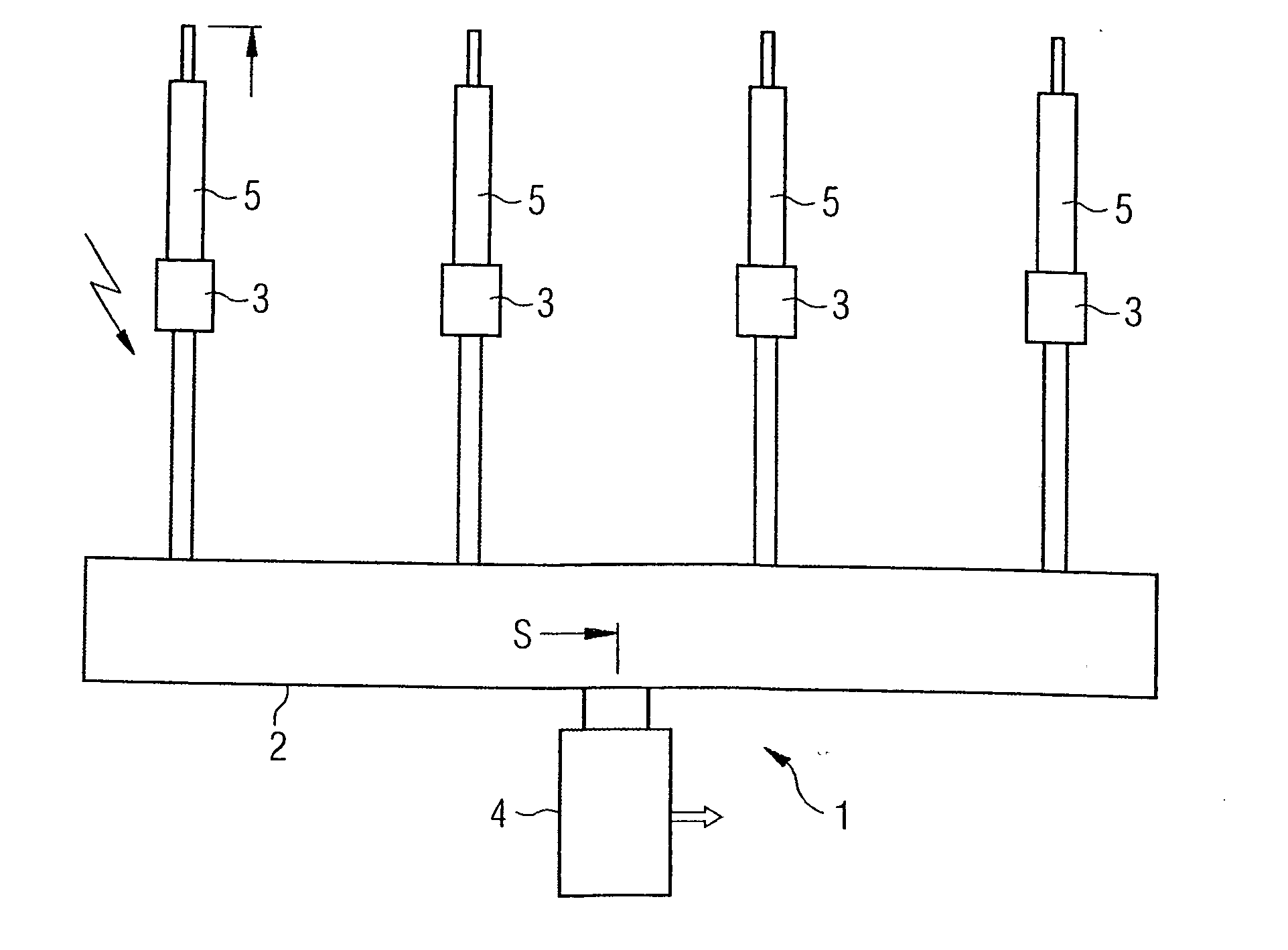
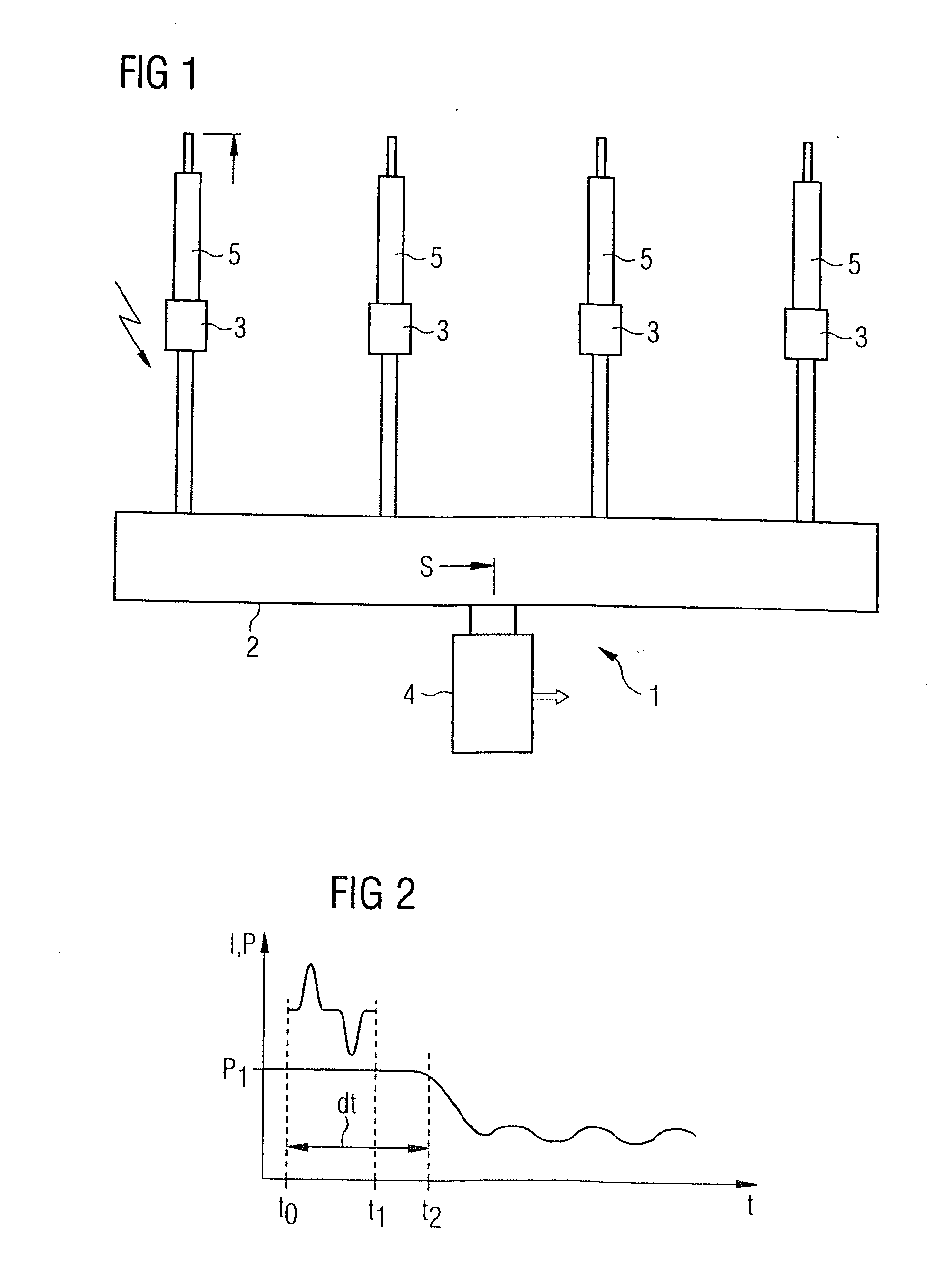
[0027]FIG. 1 is a diagram of a common rail fuel-injection system 1 such as can be used in for example a four-cylinder diesel engine. In particular it has a high-pressure vessel known as a common rail 2 containing fuel (in this case diesel fuel) under very high pressure. The high pressure is created by a fuel pump and a control loop which have been omitted from FIG. 1 for the sake of clarity. It is important that the pressure in the rail 2 is detected by a pressure sensor 4. The pressure sensor 4 delivers a signal to a control circuit which re-adjusts the pressure in the rail 2 according to the specified conditions.

[0028] Four injection valves or injectors 5 are connected output side, and at the end of each injector is an injector needle through which when the injector 5 is actuated the fuel can escape and be injected into the combustion chamber in the engine. The injectors 5 are operated by actuators 3 which typically work on the piezoelectric principle and extend reversibly in the...


PUM


Abstract

In fuel reservoir injection systems also known as common rail fuel-injection systems (1) for motor vehicles the problem exists that for a defined quantity of fuel that is about to be injected it is necessary to take into account not only the predominant pressure of the fuel but also its temperature. It is difficult to install and use a temperature sensor to detect the fuel temperature. The invention therefore proposes a method and a device for determining the temperature (T) from the pressure (P) measured by the pressure sensor (4) and the sound-propagation velocity (V) of a shock wave triggered at the moment of injection.

Description

CROSS REFERENCE TO RELATED APPLICATION [0001] This application is a continuation of copending International Application No. PCT / EP03 / 13381 filed Nov. 27, 2003 which designates the United States, and claims priority to German application no. 103 01 264.8 filed Jan. 15, 2003.TECHNICAL FIELD OF THE INVENTION [0002] The invention provides for a method and a device for determining the temperature of fuel in a fuel reservoir injection system, in particular in the common rail injection system of a motor vehicle, in which the fuel flows via a high-pressure vessel (common rail) to connected injection valves (injectors) in the fuel-injection system, said valves being controllable by appropriate actuators, and in which the pressure of the fuel in the common rail is detected by a pressure sensor. As is already known, in a fuel reservoir injection system, which in the case of motor vehicle engines is also usually known as a common rail injection system, a fuel-injection cycle is controlled by me...

Claims


Application Information

Patent Timeline
Patent Type & Authority Applications(United States)
IPC IPC(8): F02D41/38
CPCF02D41/3809F02D2250/04F02D2200/0606F02D2200/0602
Inventor FRITSCH, JURGENHIRN, RAINERVALERO-BERTRAND, DIEGOWIRKOWSKI, MICHAEL
Owner CONTINENTAL AUTOMOTIVE GMBH
Why Eureka
Try Eureka