Thick coated combustor liner

a combustor lining, thick coating technology, applied in the direction of machines/engines, mechanical equipment, light and heating equipment, etc., can solve the problems of obstructing the proper performance of cooling nuggets, reducing the available cooling air provided to the combustor liners, and reducing the thermal barrier coating thickness, so as to achieve enhanced thermal protection and thin coating thickness

Inactive Publication Date: 2005-03-10
GENERAL ELECTRIC CO
View PDF17 Cites 25 Cited by
  • Summary
  • Abstract
  • Description
  • Claims
  • Application Information

AI Technical Summary

Benefits of technology

[0013] Accordingly, it is desired to provide an improved combustor liner having thicker thermal barrier coating thereon for enjoying the enhanced thermal protection thereof without obstructing performance of the cooling nuggets.

Problems solved by technology

The efficiency of the engine is directly related to the temperature of the combustion gases which temperature is suitably limited for achieving a suitable life of the combustor and hot components downstream therefrom.
Although engine efficiency may be increased by increasing the temperature of the combustion gases, the ability to cool the combustor liners with a fixed flowrate of air is limited.
Furthermore, it desired to decrease the available cooling air provided to the combustor liners for lowering NOx exhaust emissions.
Although it is possible to increase the thickness of conventional thermal barrier coatings, such thicker coatings can obstruct the proper performance of the cooling nuggets and reduce their cooling effectiveness.
Since the size of the cooling nuggets is preferably limited for limiting size and weight of the combustor, the introduction of thicker thermal barrier coating on the liner necessarily obstructs flow discharge from the nuggets.
Without the introduction of such a uniformly thick thermal barrier coating on a combustor liner, the combustor liner will not be uniformly protected from the hot combustion gases.

Method used


Image

  • Thick coated combustor liner
  • Thick coated combustor liner
  • Thick coated combustor liner

Examples


Embodiment Construction

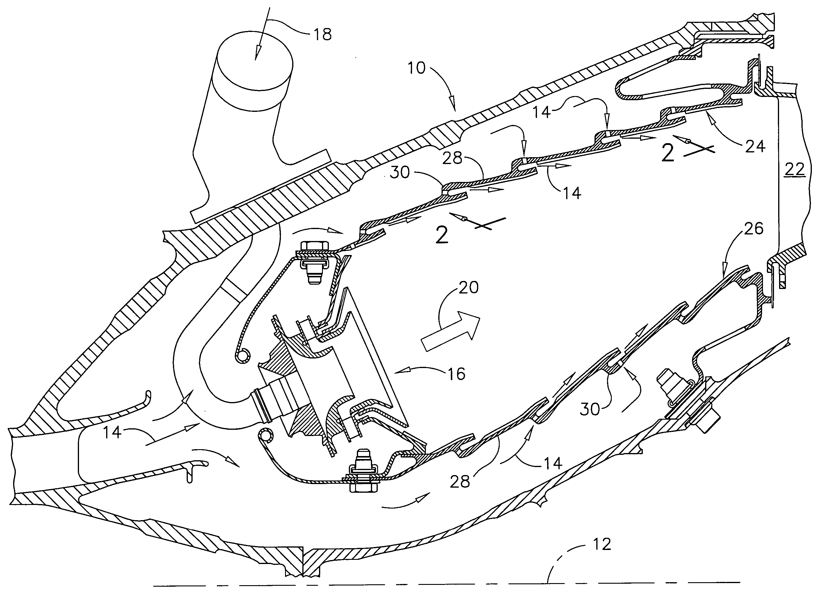
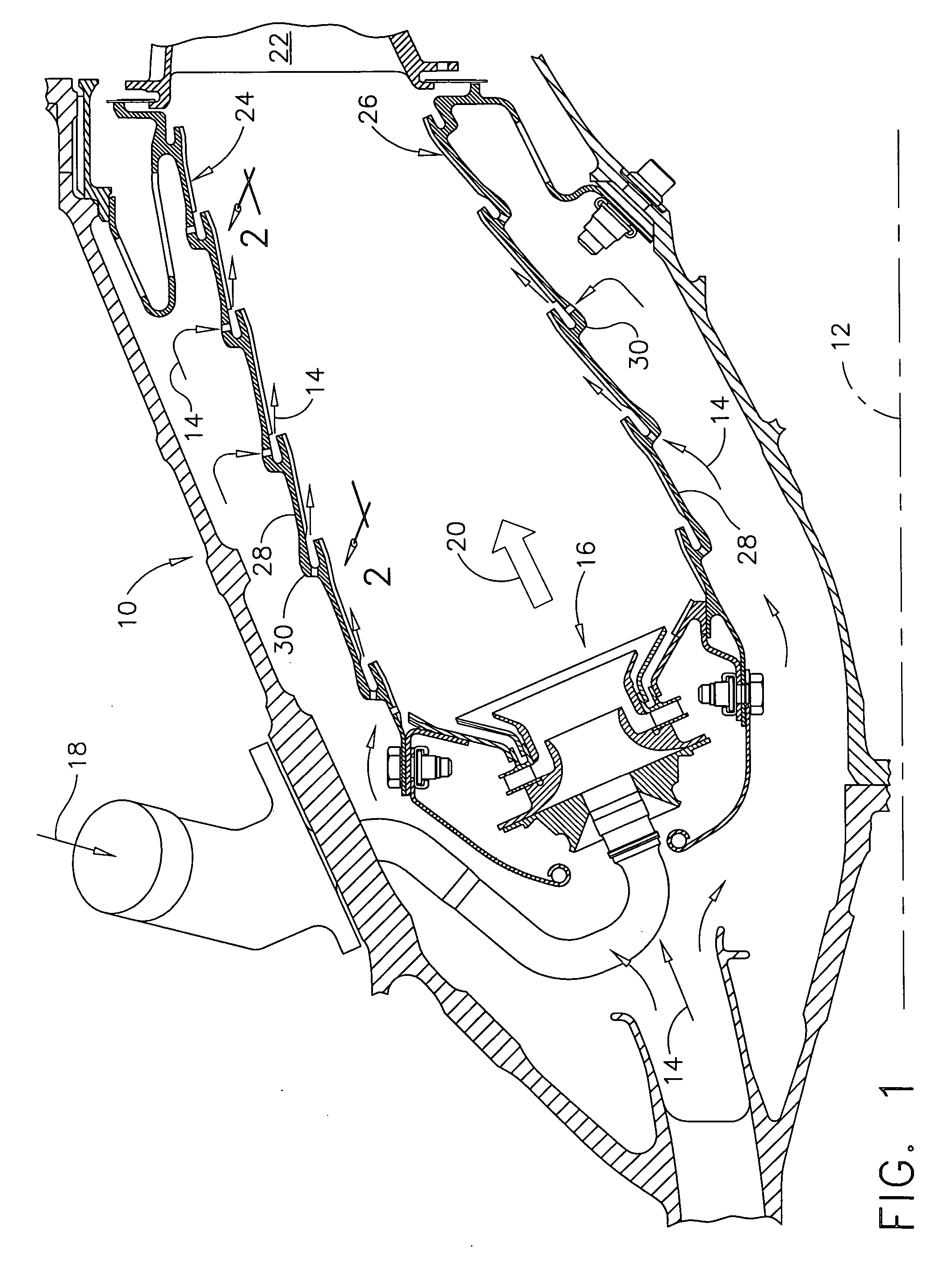
[0020] Illustrated in FIG. 1 is an annular combustor 10 which is axisymmetrical about a longitudinal or axial centerline axis 12. The combustor is suitably mounted in a gas turbine engine having a multistage axial compressor (not shown) configured for pressurizing air 14 during operation. A row of carburetors 16 introduces fuel 18 into the combustor which is ignited for generating hot combustion gases 20 that flow downstream therethrough.

[0021] A turbine nozzle 22 of a high pressure turbine is disposed at the outlet end of the combustor for receiving the combustion gases, which are redirected through a row of high pressure turbine rotor blades (not shown) that rotate a disk and shaft for powering the upstream compressor. A low pressure turbine (not shown) is typically used for extracting additional energy for powering an upstream fan in a typical turbofan aircraft gas turbine engine application, or an output shaft in a typical marine and industrial application.

[0022] The exemplary...


PUM


Abstract

A combustor liner includes panels joined together at a cooling nugget including a bridge and a lip extending therefrom. The lip defines a slot terminating in an outlet. Thermal barrier coating covers inboard surfaces of the panels and lip with a nominal thickness. The lip has a distal end at the slot outlet which is spaced from the coating aft of the slot less than about the coating nominal thickness.

Description

BACKGROUND OF THE INVENTION [0001] The present invention relates generally to gas turbine engines, and, more specifically, to combustor liners therein. [0002] In a gas turbine engine air is pressurized in a compressor and mixed with fuel and burned in a combustor. The combustion gases are channeled through a high pressure turbine which extracts energy therefrom for powering the compressor. A low pressure turbine follows the high pressure turbine for extracting additional energy from the gases for powering an upstream fan in a typical aircraft turbofan gas turbine engine application. In marine and industrial applications, the low pressure turbine instead powers an output shaft. [0003] A typical combustor includes radially outer and inner liners joined together by an annular dome at upstream ends thereof for defining radially therebetween an annular combustion chamber. The dome includes carburetors having corresponding fuel injectors and air swirlers that introduce corresponding mixtu...

Claims


Application Information

Patent Timeline
Patent Type & Authority Applications(United States)
IPC IPC(8): F23R3/42F02C7/18F23M5/08F23R3/00F23R3/06F23R3/08
CPCF23M5/085F23M2900/05004F23R3/007Y02T50/675F23R2900/03042Y02T50/67F23R3/08Y02T50/60
Inventor MCMASTERS, MARIE ANN
Owner GENERAL ELECTRIC CO
Why Eureka
Try Eureka