Thermal barrier coating system and process therefor

a technology of thermal barrier coating and coating system, which is applied in the direction of waterborne vessels, machines/engines, natural mineral layered products, etc., can solve the problems of platform cracking, difficult air cooling of blade platforms, and particularly demanding requirements, so as to reduce detrimental temperature gradients within components and reduce temperatures on the component surfa

Active Publication Date: 2007-12-11
GENERAL ELECTRIC CO
View PDF12 Cites 13 Cited by
  • Summary
  • Abstract
  • Description
  • Claims
  • Application Information

AI Technical Summary

Benefits of technology

[0007]The present invention provides a coating process and a TBC system suitable for protecting surfaces of a component subjected to a hostile thermal environment, notable examples of which are airfoil components of gas turbine engines. The TBC system is selectively deposited as multiple ceramic layers on different surface regions of the component in a manner that reduces temperatures on the component surfaces, as well as reduces detrimental temperature gradients within the component.
[0009]A significant advantage of this invention is that, because of the selective deposition of the second ceramic layer, the TBC system can be deposited whose thickness is tailored for different surface regions of a component, without resulting in excessive TBC thickness on surface regions where excess TBC would be detrimental. For example, the first layer of TBC can be deposited on both the airfoil and platform portions of an air-cooled blade, after which the second layer of TBC is selectively deposited on only the platform portion of the blade. In this manner, a relatively thick TBC can be deposited on the blade platform to provide additional thermal protection while avoiding excess TBC that would block the cooling holes of the airfoil.

Problems solved by technology

This requirement is particularly demanding due to the different coefficients of thermal expansion between ceramic materials and the superalloys typically used to form turbine engine components.
Attempts to air cool blade platforms are complicated by the desire to avoid internal and surface features that could increase stress concentrations which, in combination with thermal gradients typically within platforms, can lead to cracking.
Though blade platforms generally see lower temperatures than blade tips, the thermal gradient within a platform can result in platform cracking if the airfoil is effectively cooled but the platform is not.
However, TBC thicknesses capable of adequately reducing the surface temperature of a platform risk plugging the airfoil cooling holes.
While the relative amount of TBC deposited on the platform can be increased by tilting the blade relative to the vapor source, the limitations of existing EBPVD equipment are such that a sufficiently thick TBC cannot be deposited on the platform without also depositing an excessively thick TBC on the airfoil.
Another problem is that the erosion resistance of EBPVD TBC decreases to some degree if the surface being coated is other than parallel to the surface of the vapor source.
As such, tilting a blade to increase the relative amount of TBC deposited on the platform can unacceptably reduce the erosion resistance of the TBC on the airfoil.
Finally, the deposition rate on an inclined surface is relatively lower, thus increasing the time and cost of the deposition process.

Method used


Image

  • Thermal barrier coating system and process therefor
  • Thermal barrier coating system and process therefor
  • Thermal barrier coating system and process therefor

Examples


Embodiment Construction

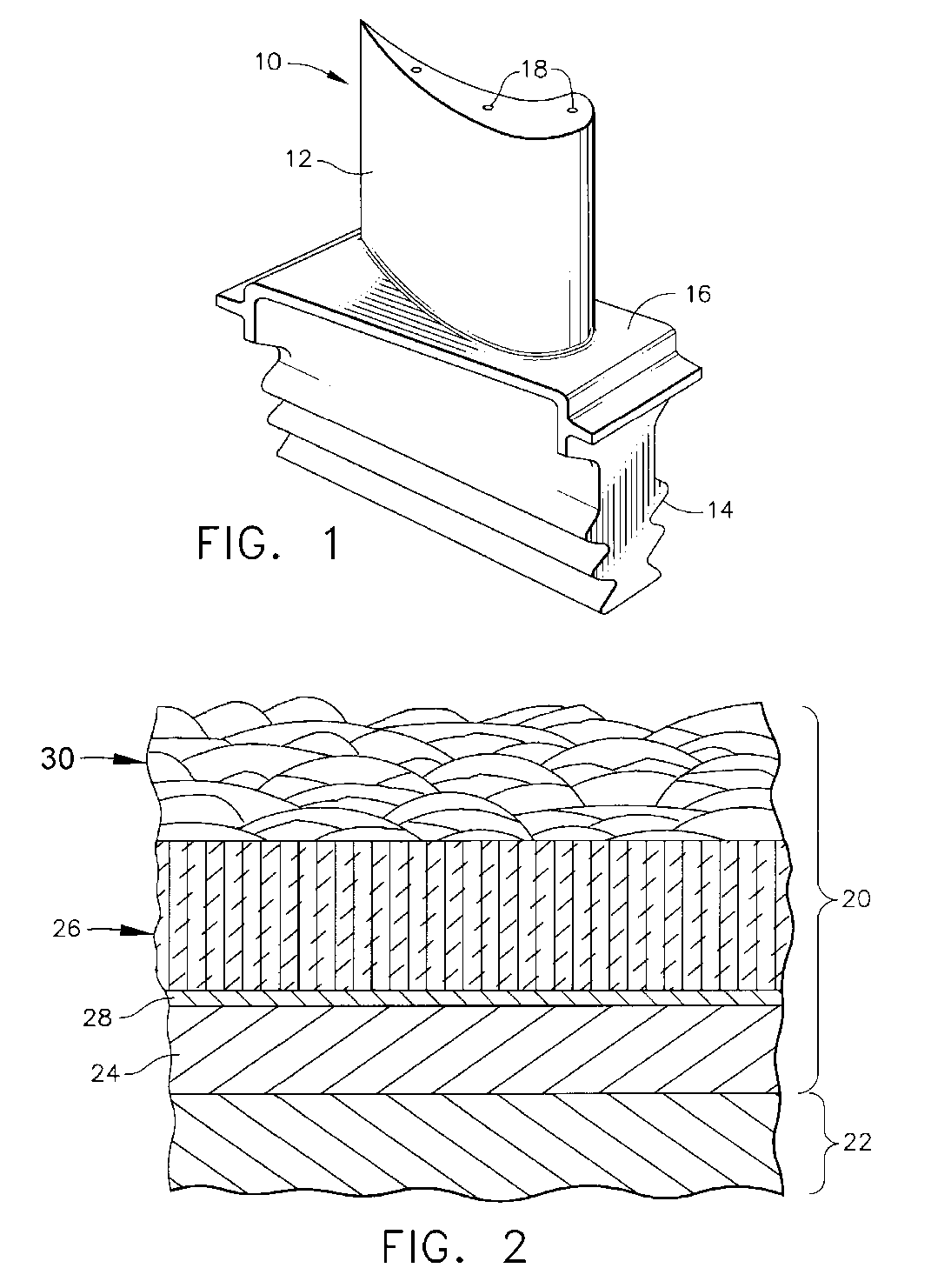
[0014]The present invention is generally applicable to components subjected to high temperatures, and particularly to components such as the high pressure turbine (HPT) blades and vanes of gas turbine engines. An example of an HPT blade 10 is shown in FIG. 1. The blade 10 has an airfoil 12, a dovetail 14 by which the blade 10 is anchored to a turbine disk (not shown), and a platform 16 therebetween. During operation of the gas turbine engine, the airfoil 12 and platform 16 are directly exposed to hot combustion gases. Significant cooling of the airfoil 12 is achieved by flowing bleed air through internal passages (not shown) within the blade 10. The bleed air exits the airfoil 12 through cooling holes 18 to transfer heat from the blade 10. While the advantages of this invention will be described with reference to components of a gas turbine engine, such as the high pressure turbine blade 10 shown in FIG. 1, the teachings of this invention are generally applicable to other components...


PUM

PropertyMeasurementUnit
thicknessaaaaaaaaaa
thicknessaaaaaaaaaa
thicknessaaaaaaaaaa

Abstract

A coating process and TBC system suitable for protecting the surface of a component subjected to a hostile thermal environment. The TBC system has a first layer with a columnar microstructure, and a second layer on the first layer and with a microstructure characterized by irregular flattened grains. According to one aspect, the first layer is present and the second layer is not present on a first surface portion of the component, and the first and second layers are both present on a second surface portion of the component. According to another aspect, the first and second layers contain the same base ceramic compound.

Description

BACKGROUND OF THE INVENTION[0001]The present invention generally relates to thermal barrier coating systems for components exposed to high temperatures, such as airfoil components of gas turbine engines. More particularly, this invention is directed to a thermal barrier coating system and process for selectively depositing multiple ceramic layers on different surface regions of a component to reduce surface temperatures and temperature gradients within the component.[0002]Components within the hot gas path of a gas turbine engine are often protected by a thermal barrier coating (TBC) system. TBC systems include a thermal-insulating topcoat, also referred to as the thermal barrier coating or TBC. Ceramic materials are used as TBC materials because of their high temperature capability and low thermal conductivity. The most common TBC material is zirconia (ZrO2) partially or fully stabilized by yttria (Y2O3), magnesia (MgO) or another alkaline-earth metal oxide, ceria (CeO2) or another...

Claims


Application Information

Patent Timeline
Patent Type & Authority Patents(United States)
IPC IPC(8): B32B15/00F03B3/12
CPCC23C4/04C23C26/00F01D5/288C23C28/321C23C28/325C23C28/345C23C28/3455C23C28/3215Y10T428/12611
Inventor WORTMAN, DAVID JOHNBLANK, JONATHAN PAULKEITH, SEAN ROBERT
Owner GENERAL ELECTRIC CO
Why Eureka
Try Eureka