Ceramic matrix composite turbine component with engineered surface features retaining a thermal barrier coat

a composite turbine and engineered surface technology, applied in the direction of machines/engines, stators, liquid fuel engines, etc., can solve the problems of crack formation in the tbc layer and its delamination from the superalloy surface, adversely affecting inter-layer adhesion at the cmc/tbc interface, and present new and different thermal expansion mismatch and adhesion challenges, etc., to achieve enhanced tbc retention, increased surface area, and improved adherence ability

Inactive Publication Date: 2018-02-01
SIEMENS AG
View PDF4 Cites 12 Cited by
  • Summary
  • Abstract
  • Description
  • Claims
  • Application Information

AI Technical Summary

Benefits of technology

[0008]Exemplary embodiments described herein enhance TBC retention on CMC components in combustion turbine engines, by cutting engineered surface features (“ESFs”) within the surface of the CMC ceramic core and the embedded ceramic fibers. The ESFs mechanically interlock the CMC structure, and in particular the fibers bundles, to the TBC, and provide increased surface area and additional interlocking for interlayer adhesion. A thermally sprayed or vapor deposited or solution / suspension plasma sprayed TBC is applied over and coupled to the ceramic core outer surface and the ESFs. Increased adherence capabilities afforded by the ESFs facilitate application of thicker TBC layers to the component, which increases insulation protection for the underlying CMC structure / layer. The increased adhesion surface area and added mechanical interlocking of the respective materials facilitates application of greater TBC layer thickness to the CMC substrate without risk of TBC delamination. The greater TBC layer thickness in turn provides more thermal insulation to the CMC structure, for higher potential engine operating temperatures and efficiency. In some embodiments, the CMC component covers an underlying substrate, such as a superalloy metallic substrate. In other embodiments, the CMC component is a sleeve over a metallic substrate. In other embodiments, the CMC component has no underlying metallic substrate, and provides its own internal structural support. In additional embodiments, a plurality of CMC components are joined together to form a larger, composite CMC component, such as a laminated turbine blade or vane.
[0011]Exemplary embodiments of the invention feature a ceramic matrix composite (“CMC”) component for a combustion turbine engine has a solidified ceramic core, with a three-dimensional preform of ceramic fibers, embedded therein. Engineered surface features (“ESFs”) cut into an outer surface of the core and fibers of the preform. A thermally sprayed, or vapor deposited, or solution / suspension plasma sprayed thermal barrier coat (“TBC”) is applied over and coupled to the core outer surface and the ESFs. The ESFs provide increased surface area and mechanically interlock the TBC, improving adhesion between the ceramic core and the TBC.

Problems solved by technology

However, TBC application over CMC or superalloy substrates presents new and different thermal expansion mismatch and adhesion challenges.
In the case of TBC application over superalloy substrates, the superalloy material expands more than the overlying TBC material, which in extreme cases leads to crack formation in the TBC layer and its delamination from the superalloy surface.
Along with thermal mismatch challenges, metallic substrate / TBC interfaces have adhesion challenges.
Many CMC materials already contain oxides in the solidified ceramic core and in their embedded ceramic fibers, which adversely affect inter-layer adhesion at the CMC / TBC interface.
Therefore, application of the TBC on the CMC surface of the component without subsequent delamination during engine operation is difficult.
Depending upon the local macro roughness of the embedded ceramic fibers in the preform, and the infiltration characteristics of the ceramic material, which embed the preform into the solidified ceramic core, the adhesion of TBC coatings, is generally poorer than that of TBC coating on metallic substrates.
TBC / CMC adhesion is particularly poor where the preform embedded fibers are oriented parallel to the component surface.
Unfortunately, limiting the TBC layer thickness undesirably limits its insulation properties.

Method used


Image

  • Ceramic matrix composite turbine component with engineered surface features retaining a thermal barrier coat
  • Ceramic matrix composite turbine component with engineered surface features retaining a thermal barrier coat
  • Ceramic matrix composite turbine component with engineered surface features retaining a thermal barrier coat

Examples


Embodiment Construction

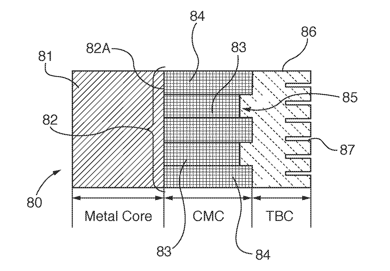
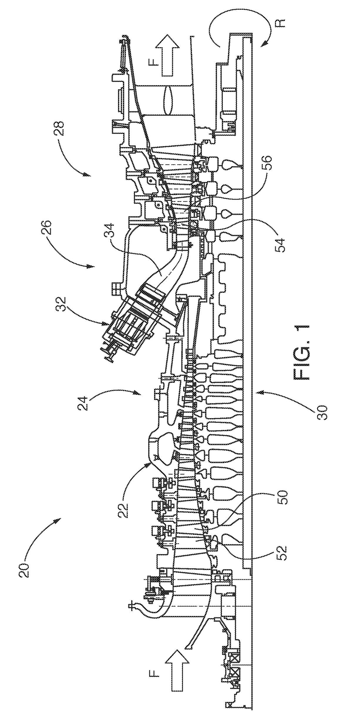
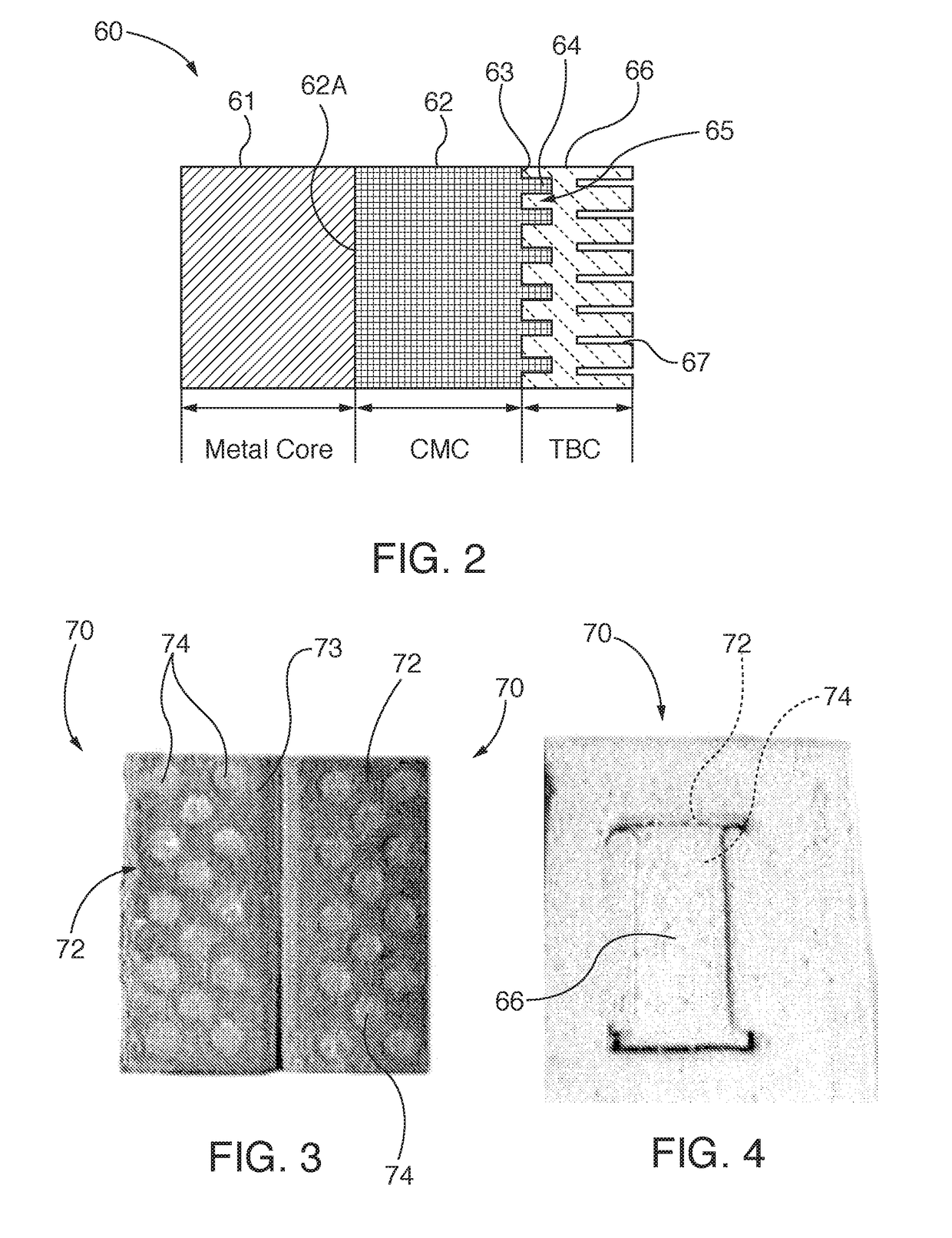
[0026]Exemplary embodiments of the invention are utilized in combustion turbine engines. In some embodiments, the ceramic matrix composite (“CMC”) components of the invention are utilized as insulative covers or sleeves for other structural components, such as metallic superalloy components. In other embodiments, the CMC component is structurally self-supporting. Embodiments of the CMC components of the invention are combined to form composite structures, such as turbine blades or vanes, which are structurally self-supporting or which cover other structural elements. Embodiments of the CMC components of the invention have a solidified ceramic core, with a three-dimensional preform of ceramic fibers, embedded therein. Engineered surface features (“ESFs”) cut into an outer surface of the core and fibers of the preform. A thermally sprayed, or vapor deposited, or solution / suspension plasma sprayed thermal barrier coat (“TBC”) is applied over and coupled to the core outer surface and th...


PUM

PropertyMeasurementUnit
thicknessaaaaaaaaaa
heightaaaaaaaaaa
heightaaaaaaaaaa

Abstract

An oxide and non-oxide based ceramic matrix composite (“CMC”) component for a combustion turbine engine has a solidified ceramic core with a three-dimensional preform of ceramic fibers, embedded therein. Engineered surface features (“ESFs”) are cut into an outer surface of the core and fibers of the preform. A thermal barrier coat (“TBC”) is applied over and coupled to the core outer surface and the ESFs. The ESFs provide increased surface area and mechanically interlock the TBC, improving adhesion between the ceramic core and the TBC.

Description

PRIORITY CLAIM[0001]This application claims priority to International Application No. PCT / US15 / 16318, filed Feb. 18, 2015, and entitled “TURBINE COMPONENT THERMAL BARRIER COATING WITH CRACK ISOLATING ENGINEERED GROOVE FEATURES”; and International Application No. PCT / US15 / 16331, filed Feb. 18, 2015, and entitled “TURBINE COMPONENT THERMAL BARRIER COATING WITH CRACK ISOLATING ENGINEERED SURFACE FEATURES”. The entire contents of both priority documents are incorporated by reference herein.TECHNICAL FIELD[0002]The invention relates to components for combustion turbine engines, with ceramic matrix composite (“CMC”) structures that are in turn insulated by a thermal barrier coating (“TBC”), and methods for making such components. More particularly, the invention relates to engine components for combustion turbines, with ceramic matrix composite (“CMC”) structures, having engineered surface features (“ESFs”) that anchor the TBC.BACKGROUND[0003]CMC structures comprise a solidified ceramic c...

Claims


Application Information

Patent Timeline
Patent Type & Authority Applications(United States)
IPC IPC(8): C04B41/81C23C16/04C04B41/91C23C4/134
CPCC04B41/81C23C4/134C23C16/045C04B41/91F01D5/282F01D9/023F04D29/324F04D29/542F04D29/5853F05D2220/32F05D2240/35F05D2230/90F05D2230/10F05D2300/6033F05D2300/5023F01D11/08F01D11/12F01D5/14F01D5/18F01D5/186F01D5/28F01D5/288Y02T50/60F01D5/147F01D11/122F05D2230/312F05D2230/313F05D2250/132F05D2250/294F05D2250/60F05D2300/502
Inventor SUBRAMANIAN, RAMESHWALTER, STEFFENVAN DER LAAG, NIELSRETTIG, UWE
Owner SIEMENS AG
Why Eureka
Try Eureka