Temperature control device of evaporator

Inactive Publication Date: 2005-03-10
HONDA MOTOR CO LTD
View PDF4 Cites 10 Cited by
  • Summary
  • Abstract
  • Description
  • Claims
  • Application Information

AI Technical Summary

Benefits of technology

[0012] In accordance with this arrangement, since the flow rate of the exhaust gas is determined by calculation based on the intake air volume and the air/fuel ratio, which are parameters that indicate the operating conditions of the engine, the exhaust gas flow rate can be calculated with high precision an

Problems solved by technology

However, in the arrangement disclosed in Japanese Patent Application Laid-open No. 60-64101, due to a delay in pumping fuel and a mechanical delay in a governor mechanism, the amount of fuel suppl

Method used


Image

  • Temperature control device of evaporator
  • Temperature control device of evaporator
  • Temperature control device of evaporator

Examples


Example

[0014] The first embodiment of the present invention is explained below with reference to FIG. 1 to FIG. 6.

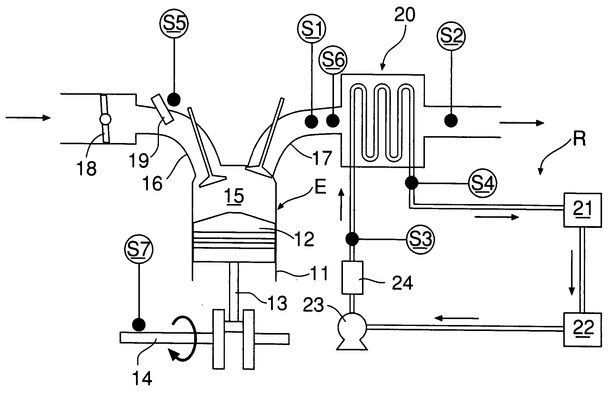
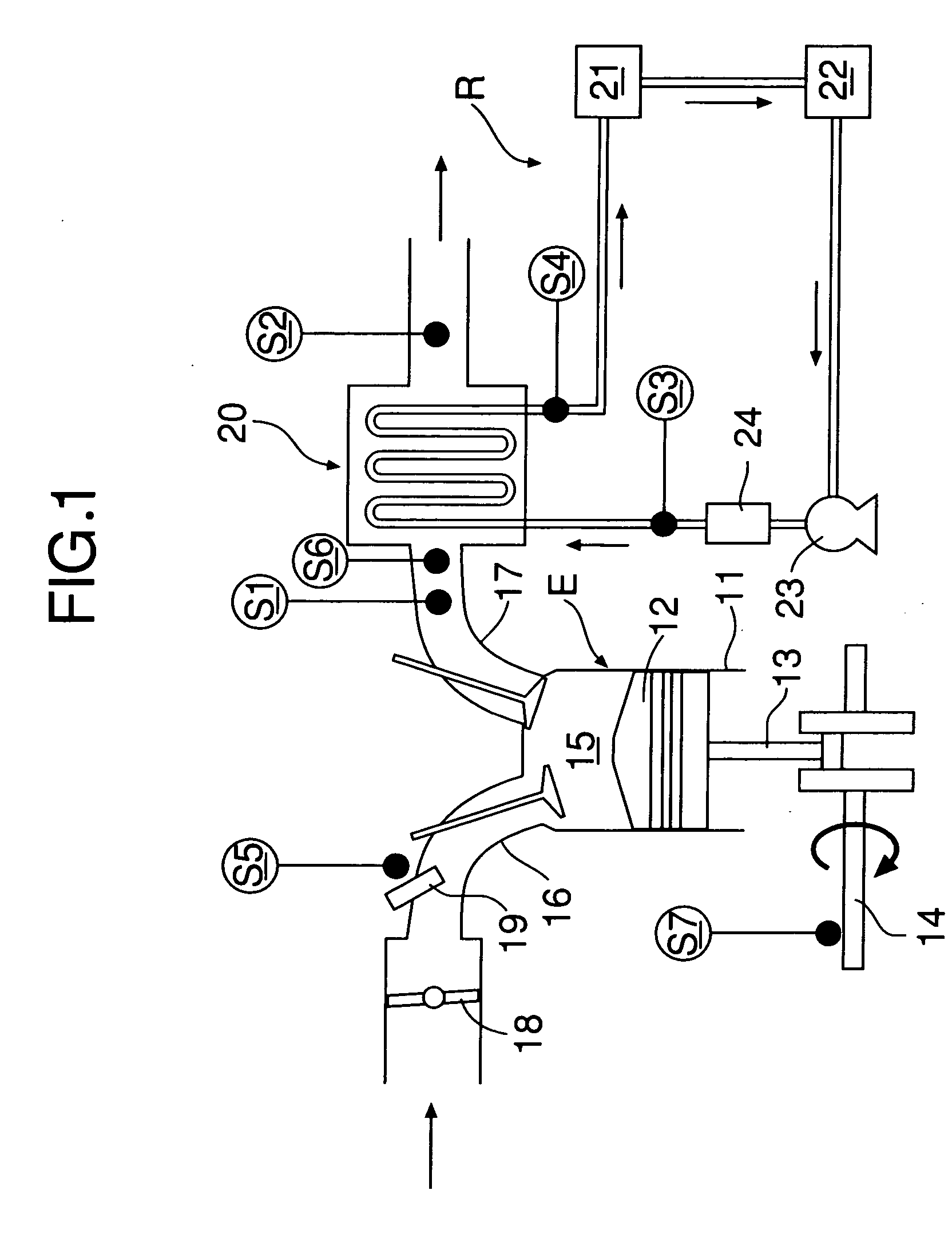
[0015] As shown in FIG. 1 and FIG. 2, a gasoline engine E includes a cylinder 11, a piston 12 that is slidably fitted in the cylinder 11, a connecting rod 13 having a little end connected to the piston 12, a crankshaft 14 connected to a big end of the connecting rod 13, a combustion chamber 15 defined between the cylinder 11 and the piston 12, an intake port 16 that communicates with the combustion chamber 15, an exhaust port 17 that communicates with the combustion chamber 15, a throttle valve 18 provided in the intake port 16, a fuel injection valve 19 provided in the intake port 16, and an evaporator 20 provided in the exhaust port 17.

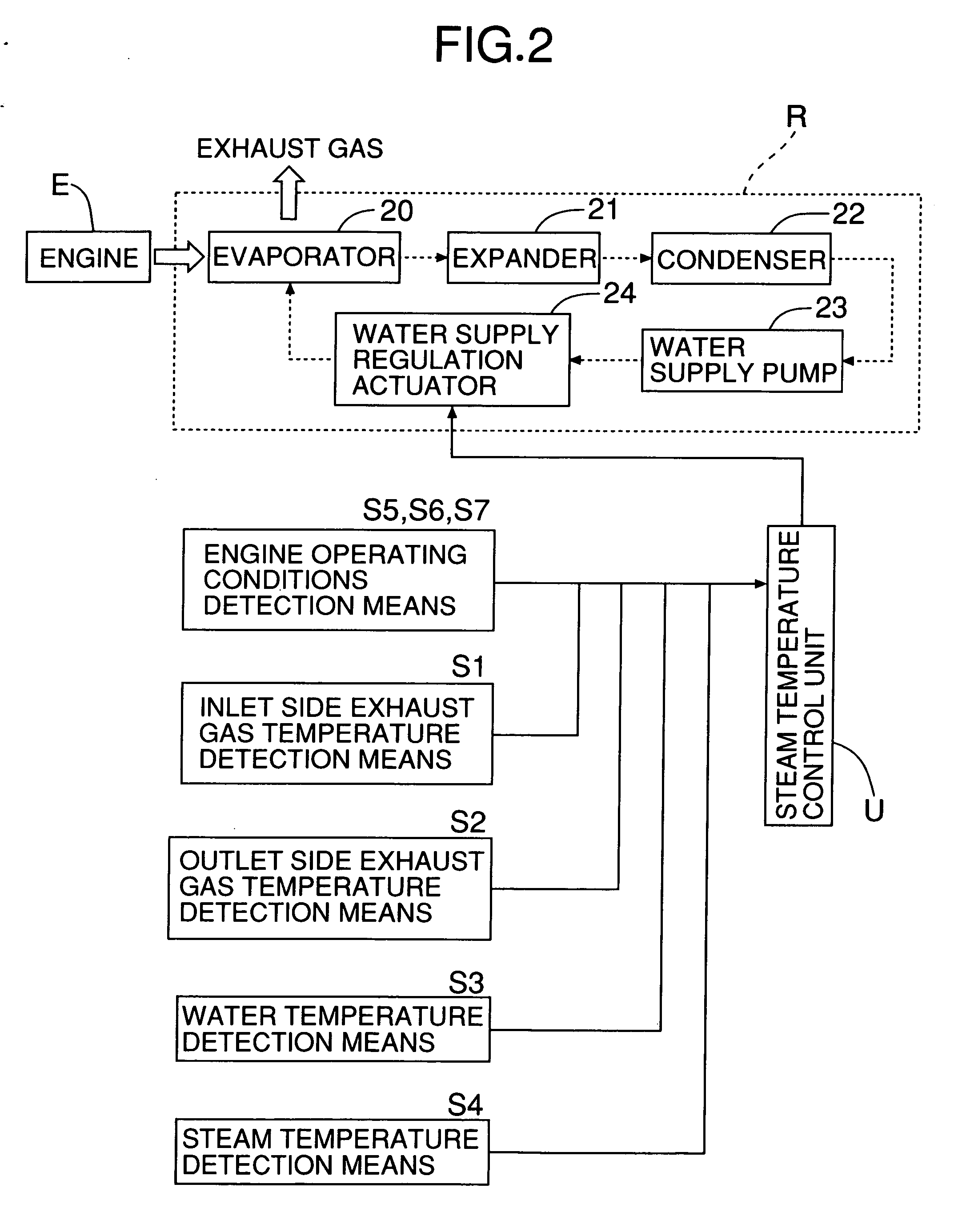
[0016] A Rankine cycle system R for recovering pressure energy and thermal energy of exhaust gas of the engine E and converting them into mechanical energy includes the evaporator 20 for generating steam as a gas-phase working medium by heati...

Example

[0032] A second embodiment of the present invention is now explained with reference to FIG. 7.

[0033] In the second embodiment, the method for determining the exhaust gas flow rate Gmix by calculation is different from that of the first embodiment, but the rest of the structure and the operation are the same as those of the first embodiment.

[0034] In the second embodiment, in order to determine an exhaust gas flow rate Gmix there are provided, as engine operating conditions detection means, fuel injection quantity detection means S5 for detecting the amount of fuel injected per unit time and intake air volume detection means S8 (air flow meter) for detecting the mass flow rate of the intake air. The exhaust gas flow rate Gmix is then calculated from

Exhaust gas flow rate Gmix=Quantity of fuel injected per unit time×Mass flow rate of intake air.

Example

[0035] A third embodiment of the present invention is now explained with reference to FIG. 8.

[0036] In the third embodiment, the method for determining the exhaust gas flow rate Gmix by calculation is different from that of the first embodiment, but the rest of the structure and the operation are the same as those of the first embodiment.

[0037] In the third embodiment, in order to determine an exhaust gas flow rate Gmix there are provided, as engine operating conditions detection means, air / fuel ratio detection means S6 for detecting an air / fuel ratio of an engine E, and intake air volume detection means S8 (air flow meter) for detecting the mass flow rate of the intake air. The exhaust gas flow rate Gmix is then calculated from

Exhaust gas flow rate Gmix=Mass flow rate of intake air×{1 / (Air / fuel ratio+1)}.

[0038] In accordance with these second and third embodiments, the same effects as those of the first embodiment can be achieved.

[0039] Although embodiments of the present inve...


PUM


Abstract

Evaporator temperature control means (U) that, in order to make the temperature of steam generated by heating water using exhaust gas of an engine coincide with a target temperature, controls the amount of water supplied to the evaporator based on the flow rate of the exhaust gas, the temperature of the exhaust gas, the temperature of the water, and the temperature of the steam. Calculating an exhaust gas flow rate (Gmix) based on a fuel injection quantity, an air/fuel ratio, and a rotational speed of the engine improves the precision and the responsiveness of the calculation. Controlling the amount of water supplied to the evaporator based on this exhaust gas flow rate (Gmix) therefore improves the accuracy with which the steam temperature is controlled so as to make it coincide with the target temperature.

Description

FIELD OF THE INVENTION [0001] The present invention relates to an evaporator temperature control system that, in order to make the temperature of a gas-phase working medium generated by heating a liquid-phase working medium using exhaust gas of an engine coincide with a target temperature, controls the supply of the liquid-phase working medium based on the flow rate of the exhaust gas, the temperature of the exhaust gas, the temperature of the liquid-phase working medium, and the temperature of the gas-phase working medium. BACKGROUND ART [0002] An arrangement in which the exhaust gas of a diesel engine is guided to an evaporator so as to heat water and generate steam, and the pressure energy and the thermal energy of this steam are used to operate an expander and generate mechanical energy is known from Japanese Patent Application Laid-open No. 60-64101. In this arrangement the flow rate of the exhaust gas is used as one of the parameters with which control is carried out in order ...

Claims


Application Information

Patent Timeline
IPC IPC(8): F01K23/06F01K23/10F01N5/02
CPCF01K23/065Y02T10/16F01N5/02F01K23/101Y02T10/12
Inventor NAGATANI, SHUJIBABA, TSUYOSHIIBARAKI, SHIGERUSATO, AKIHISAMAEDA, SUSUMU
Owner HONDA MOTOR CO LTD
Why Eureka
Try Eureka