Method and device for rotating a wafer

a technology of discs and wafers, which is applied in the direction of lighting and heating apparatus, charge manipulation, furnaces, etc., can solve the problems of complicated reactor walls, limited rotational speed, and difficulty in producing reactor walls of this nature, and achieves the effect of simple and inexpensive manner

Inactive Publication Date: 2005-03-10
ASM INTERNATIONAL
View PDF45 Cites 9 Cited by
  • Summary
  • Abstract
  • Description
  • Claims
  • Application Information

AI Technical Summary

Benefits of technology

[0006] The object of the present invention is to avoid these drawbacks while nevertheless maintaining the rotation of the...

Problems solved by technology

However, drilling the gas-introduction openings in this way has proven to be particularly complicated while, in addition, the rotational speed which can be achieved is limited, owing to the fact that th...

Method used


Image

  • Method and device for rotating a wafer
  • Method and device for rotating a wafer
  • Method and device for rotating a wafer

Examples


Embodiment Construction

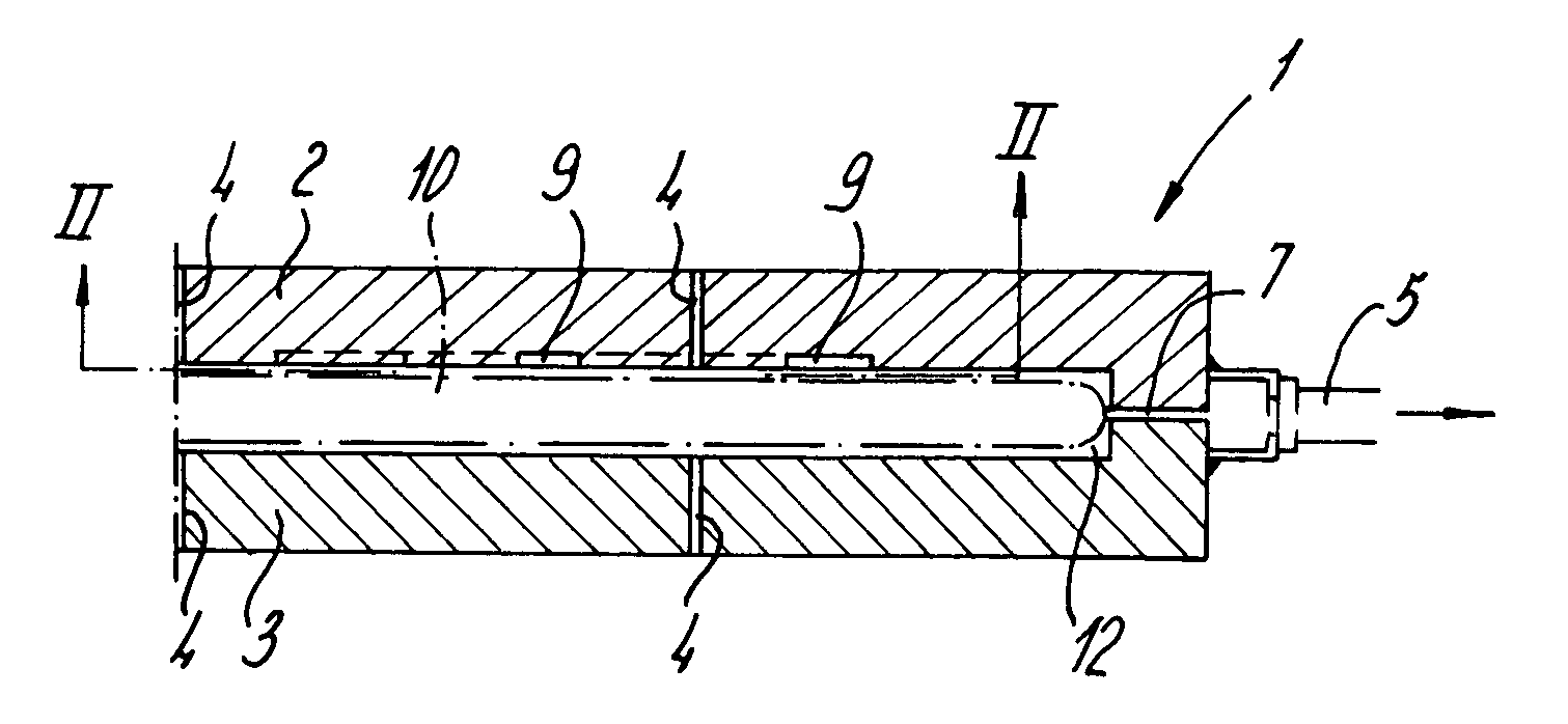
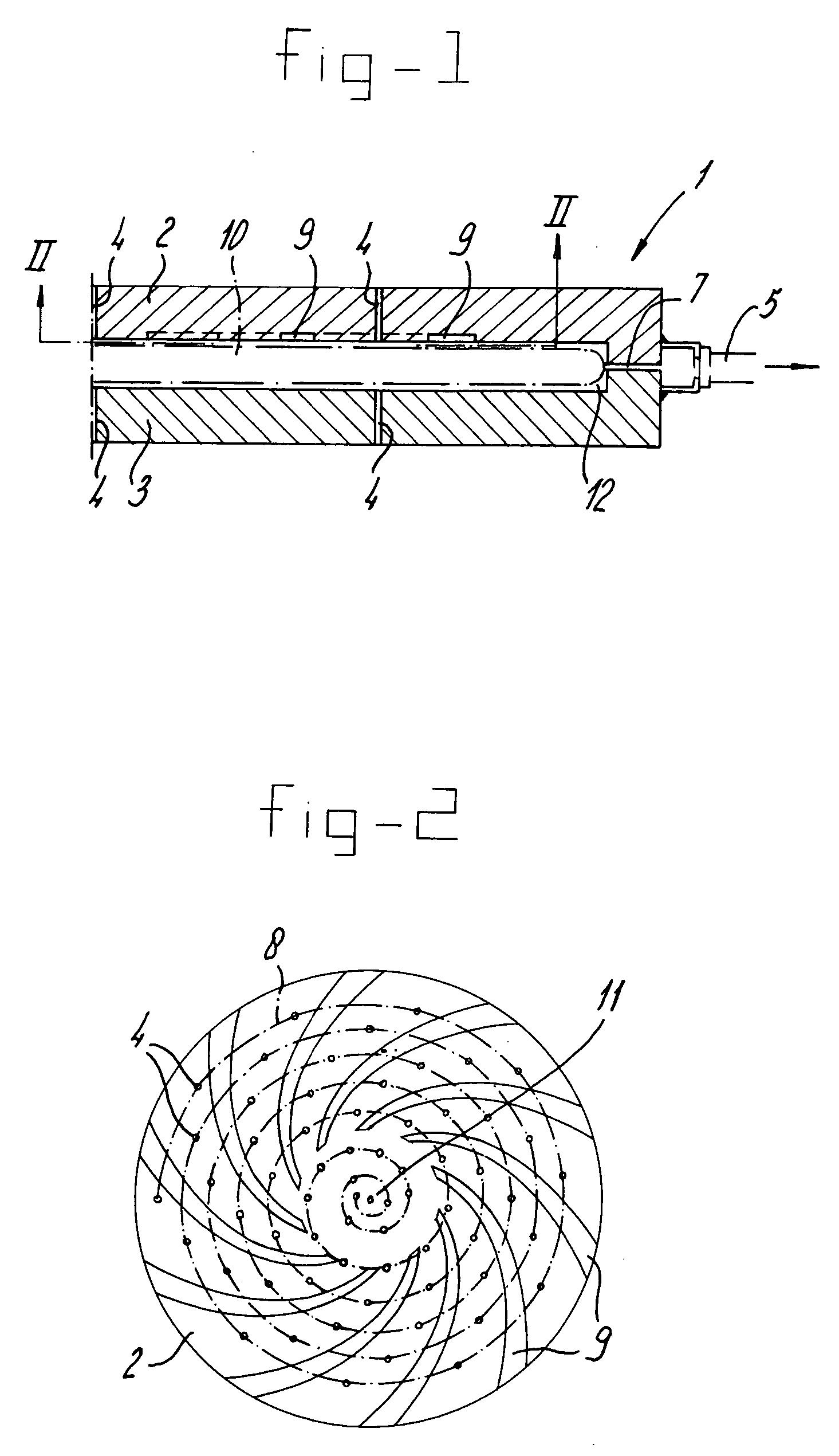
[0023] In FIG. 1, a reactor is denoted overall by 1. This reactor is shown only in part and comprises a top part 2 and bottom part 3. In any desired way, which is not illustrated, a wafer 10 may be accommodated in the chamber or treatment space 12 delimited between these parts 2 and 3. The treatment gas for the wafer is introduced via gas-introduction openings 4 both above and below the wafer, and this wafer then adopts a floating position. Gas is discharged via discharge openings 7 which may be of any conceivable form and emerge at a circumferential channel 6 which is connected to a discharge line 5.

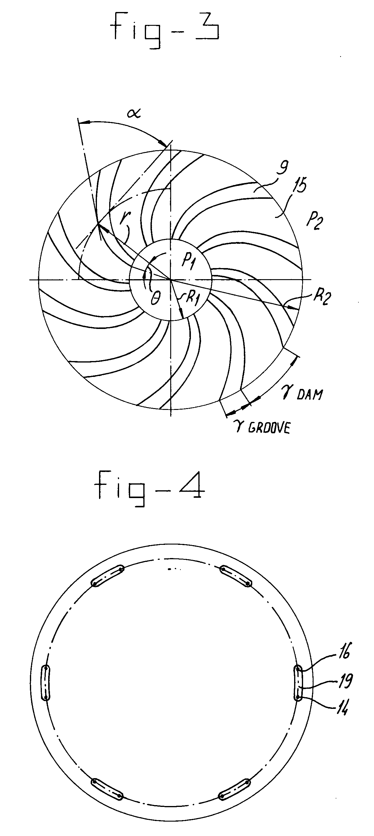
[0024] In order to impart rotation to the wafer, the top part, as can be seen from FIGS. 1 and 2, is provided with a number of grooves 9. These grooves 9 are spiral-shaped, and the origin of the spiral lies in the vicinity of the aimed centre 11 of the wafer 10. The end of the spiral is situated in the vicinity of the circumferential edge of the wafer. Grooves 9 with the shape of a log...


PUM

PropertyMeasurementUnit
Angular velocityaaaaaaaaaa
Flow rateaaaaaaaaaa
Speedaaaaaaaaaa

Abstract

Method and device for rotating a wafer which is arranged floating in a reactor. The wafer is treated in a reactor of this nature, and it is important for this treatment to be carried out as uniformly as possible. For this purpose, it is proposed to rotate the wafer by allowing the gas flow to emerge perpendicular to the surface of the wafer and then to impart to this gas a component which is tangential with respect to the wafer, thus generating rotation. This tangential component may be generated by the provision of grooves, which may be of spiral or circular design.

Description

REFERENCE TO RELATED APPLICATION [0001] This application is a divisional of U.S. application Ser. No. 09 / 936,257, filed Jan. 11, 2002, which is the U.S. national phase of International Application No. PCT / NL00 / 00154, filed Mar. 8, 2000, which claims priority from Netherlands Patent Application No. 1011487, filed Mar. 8, 1999.FIELD OF THE INVENTION [0002] The present invention relates to a method for rotating a disc-shaped object, such as a wafer, wherein along a side of said object a gas flow is directed, giving a rotation to said object, wherein said gas flow is given the rotation generating component being tangential to said object by a pattern of grooves. BACKGROUND OF THE INVENTION [0003] Such a method is known from U.S. Pat. No. 3,706,475. In this specification a device is disclosed for transporting wafers. The device comprises an elongated trajectory and from the lower side gas is added in such a way that except from a transferring movement also a rotating movement is given to...

Claims


Application Information

Patent Timeline
IPC IPC(8): B65G49/07H01L21/027H01L21/677H01L21/68
CPCH01L21/67784H01L21/00
Inventor KUZNETSOV, VLADIMIR IVANOVICHRADELAAR, SIJBRANDVAN DER SANDEN, JACOBUS CORNELIS GERARDUSRUIJL, THEO ANJES MARIA
Owner ASM INTERNATIONAL
Why Eureka
Try Eureka