Method and apparatus for multiple frequency RFID tag architecture

a radio frequency identification and tag technology, applied in the field of multiple frequency radio frequency identification tag architecture, can solve the problems of not only the associated cost of tags and readers, but also the logistics of system operation, and impede the industry acceptance of multi-frequency applications, and achieve the effect of preferably lower conductivity of electrostatic antennas

Active Publication Date: 2005-03-10
MOTOROLA SOLUTIONS INC
View PDF16 Cites 213 Cited by
  • Summary
  • Abstract
  • Description
  • Claims
  • Application Information

AI Technical Summary

Benefits of technology

[0011] Either the electrostatic or electromagnetic antennas can be comprised of two elements (e.g. two conformal plates or a dipole), and both are preferably operative at more than one frequency. The conductivity of the electrostatic antenna is preferably lower than the conductivity of the electromagnetic antenna. The electromagnetic antenna preferably couples directly to the circuitry, and may electrically intervene between the circuitry and the electrostatic antenna.

Problems solved by technology

Unfortunately, a multi-frequency approach presently means that an item needs to have multiple tags affixed to it, so that it can be successfully accounted for at each stage in the supply chain.
The associated costs of not only the tags and readers but also the system operating logistics are impeding industry acceptance of multi-frequency applications, despite their benefits.

Method used


Image

  • Method and apparatus for multiple frequency RFID tag architecture
  • Method and apparatus for multiple frequency RFID tag architecture
  • Method and apparatus for multiple frequency RFID tag architecture

Examples


Embodiment Construction

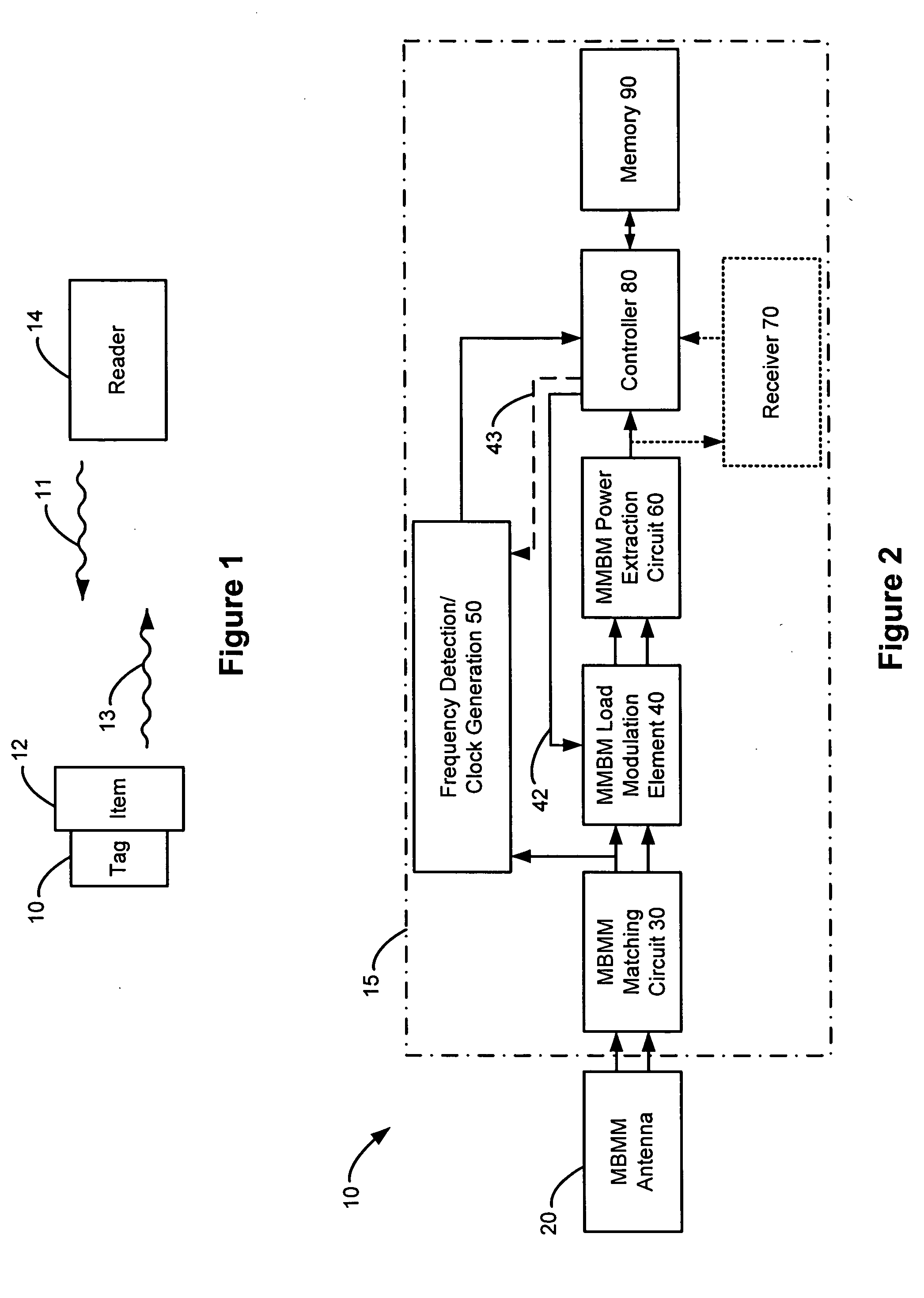
[0020]FIG. 1 shows the basic context of a RFID system in which the disclosed RFID tag 10 can be used. In the system, one or more RFID readers 14 seek to identify one or more tags 10 that have been associated with (e.g., affixed to) an item, a palette of items, etc., by irradiating the tag(s) 10. As disclosed herein, the radiation 11 from the reader 14, also known as the reader's carrier or interrogation signal, can constitute one or more frequencies (e.g., 125 kHz, 13.56 MHz, 915 MHz, and 2.45 GHz), which provides substantial benefit for both long and short range detection of the tag 10 as discussed above. Although one reader 14 is shown, it should be understood that different readers 14 can be used to broadcast different frequencies, and that multiple readers 14 can be placed in an array in a real RFID tag location application to locate tag(s) 10 over a wide area. Readers 14 can be hand-held and portable, or fixed in set locations.

[0021] The tag 10 is responsive to the various fre...


PUM


Abstract

The present invention provides a multi-band, multi-mode RFID tag that uses a single antenna structure and integrated circuit to provide asset location information at any stage of a supply chain. The unified tag design operates at multiple frequencies (or bands) using the antenna structure, for example, 125 kHz, 13.56 MHz, 915 MHz, and 2.45 GHz, and preferably operates electrostatically (at lower frequencies) and electromagnetically (ay higher frequencies). An on-chip frequency monitor in the integrated circuit automatically determines which frequency is present and derives a local clock for the tag's integrated circuit, which can vary in accordance with the frequency or which can be constant. Alternatively, a phase locked loop circuit can be used to derive a local clock signal modulated into the interrogation signal. On-chip matching and power extraction circuits derive power for the tag from the interrogation signal, which is preferably passive. Additionally, a receiver can receive data from the interrogation signal.

Description

CROSS REFERENCE TO RELATED APPLICATIONS [0001] This application is a nonprovisional application based on U.S. Provisional Application Ser. No. 60 / 501,467, filed Sep. 9, 2003, to which priority is claimed and which is incorporated herein by reference in its entirety.FIELD OF THE INVENTION [0002] The present invention relates generally to a method and apparatus for a multiple frequency radio frequency identification tag architecture. BACKGROUND OF THE INVENTION [0003] The efficiencies afforded by radio frequency identification (RFID) tags are becoming apparent in many supply chain management applications. Having timely electronic access to information concerning an item's progress through a supply chain is valuable for inventory management, controlling costs, theft prevention, shipping and labor scheduling, and many other aspects of supply chain operations. RFID is already utilized in some warehouse and shipping applications, where typically Ultra High Frequency (UHF) (e.g., 902-928 M...

Claims


Application Information

Patent Timeline
Patent Type & Authority Applications(United States)
IPC IPC(8): G06K19/07H04Q5/22
CPCG06K19/07767G06K19/0723
Inventor COLLINS, TIMOTHY J.GURNEY, DAVID P.KUFFNER, STEPHEN L.RACHWALSKI, RICHARD S.
Owner MOTOROLA SOLUTIONS INC
Why Eureka
Try Eureka