This helps you quickly interpret patents by identifying the three key elements:
Problems solved by technology
Method used
Benefits of technology
Benefits of technology
However, because the microphones are generally mounted to the inside of the roof (ceiling) or to the seat backs (rear surfaces of the seats) in order to reduce noise near occupants' ears, increasing the number of microphones not only increases the number of parts, but leads to an increase in work to provide complicated wiring to the microphones and in the computational load involved in updating the filter coefficient of the adaptive filter, and contributes to increased cost.
However, although the transfer characteristic C from the first speaker 6a to the microphone 1b is set as the filter coefficient of the FIR filter 3, and the transfer characteristic from the second speaker 6b to the control point (point A) is approximated by the same characteristic as C in the active noise cancellation system disclosed in ('477), since only the transfer characteristic G from the microphone 1b to the control point (point A) is set as the filter coefficient of the filter circuit 5, this technique has drawbacks in that the microphone 1b is actually affected by the output sound from the second speaker 6b to make it impossible to effectively reduce noise at the mounting position of the microphone 1b, and also the control point (point A) is affected by the output sound from the first speaker 6a to make it impossible to reduce noise at the control point in an effective manner.
Therefore, an object of the present invention is to overcome the above-mentioned drawbacks, and to provide an active noise cancellation system that is configured so as to reduce the number of microphones for error signal detection and avoid the above-mentioned increase in parts, the increase in the amount of work to provide complicated wiring to the microphones, and the increase in the computational load involved in updating the filter coefficient of the adaptive filter, while enabling to maintain an area in which noise can be reduced to the same level as that obtained before reducing the number of microphones.
Problems solved by technology
However, because the microphones are generally mounted to the inside of the roof (ceiling) or to the seat backs (rear surfaces of the seats) in order to reduce noise near occupants' ears, increasing the number of microphones not only increases the number of parts, but leads to an increase in work to provide complicated wiring to the microphones and in the computational load involved in updating the filter coefficient of the adaptive filter, and contributes to increased cost.
In other words, the active noise cancellation system disclosed in FIG. 1 of ('477) has the drawback of not being able to effectively reduce noise because neither the transfer characteristic from the first speaker 6a to the control point (point A), nor the transfer characteristic from the second speaker 6b to the mounting position of the microphone 1b, or the so-called cross term, is taken into account in the filter coefficient of the filter circuit 5.
Method used
Image
Click on the blue label to locate the original text in one second.
Reading with bidirectional positioning of images and text.
Examples
second embodiment
The active noise cancellation system according to the present invention will next be described.
A configuration is adopted in the active noise cancellation system according to the second embodiment whereby the filter coefficient (transfer characteristic) c of the correction filter 16c and the filter coefficient (characteristic; corresponds to prescribed value) F of the compensation filter 16e are prepared for each frequency and stored in the memory in advance so as to be retrieved by the frequency of the base signal X.
Describing this configuration, in the prior art ('344), control is performed to reduce noise according to the same adaptive feedforward control algorithm using an adaptive digital filter as described with reference to FIG. 3 such that the error signal detected by the microphone is minimized.
In the prior art, since sound or vibration is considered in a time domain in addition to the problem of the number of microphones, a high-performance, high-cost computational pr...
third embodiment
The active noise cancellation system according to the present invention will next be described.
The technique for designing the system according to the third embodiment, more specifically, the filter coefficient F of the compensation filter 16e of the system, will be described with reference to FIGS. 6 and 16, which show the speaker-to-microphone transfer characteristic mentioned above.
Focusing on the aspects that differ from the first embodiment, in the third embodiment, the distribution of the booming noise at the front and rear seats is utilized in designing the filter coefficient F. The design technique for the filter coefficient F in the first embodiment is limited to being able to control the increased sound generated at the rear seats when reducing the booming noise of the front seats. However, the technique of the third embodiment allows the booming noise at the front and rear seats to be reduced.
In the description given hereinafter, the error signal e in FIG. 16 mention...
fourth embodiment
The active noise cancellation system according to the present invention will next be described.
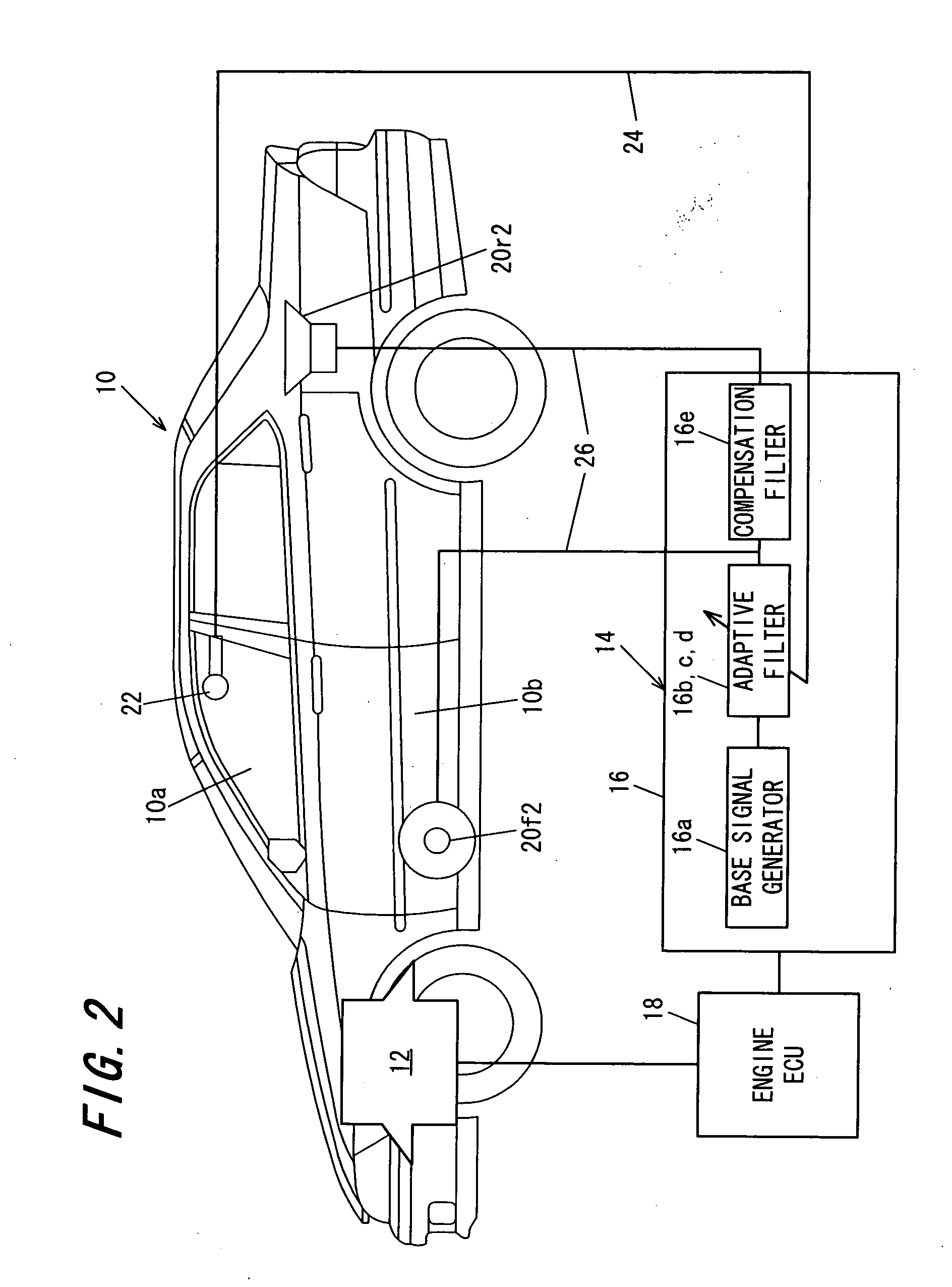
FIG. 13 is a block diagram similar to FIG. 4, but showing the configuration of the active noise cancellation system according to the fourth embodiment.
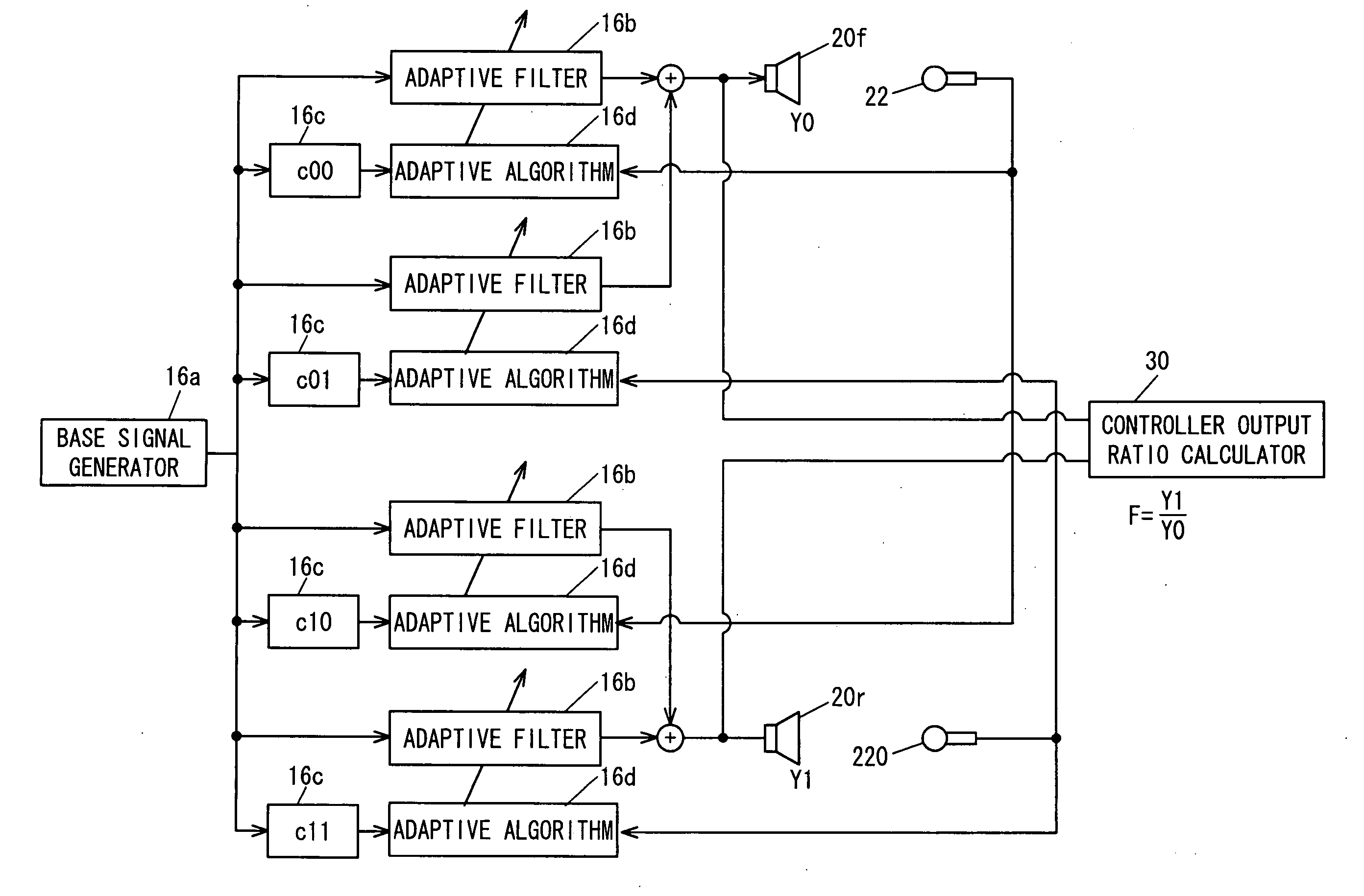
In the fourth embodiment, a microphone 220 is temporarily placed at the rear seats when the compensation filter 16e is designed, the output ratio (speaker control signal ratio) Y1 / Y0 of the controller 16 at that time is calculated or measured by a controller output ratio calculator 30, and the filter coefficient (prescribed value) F of the compensation filter 16e is set on the basis of the output ratio thus measured. Then, the microphone 220 at the rear seats is removed after the characteristic of the compensation filter 16e is determined and the system is completed.
Thus, in the active noise cancellation system according to the fourth embodiment, the microphone 220 is temporarily placed at the pseudo or simulated evaluation point 16f tha...
PUM
Abstract
In an active noise cancellation system having an adaptive filter that outputs a control signal, first and second speakers that emit a canceling signal generated based on the control signal, a microphone that detects an error signal, a correction filter that corrects the base signal by a correction value to generate a reference signal and a filter coefficient updater that successively updates the adaptive filter coefficient based on the error signal and reference signal such that the error signal is minimized, the correction value of the correction filter is set to a sum obtained by adding the transfer characteristic from the first speaker to the microphone, and a product obtained by multiplying the transfer characteristic from the second speaker to the microphone by the prescribed value, thereby enabling to reduce the number of microphones and avoid the increase in parts, the amount of work to provide complicated wiring to the microphones, and the computational load involved in updating the adaptive filter coefficient, while enabling to maintain an area in which noise can be reduced to the same level as that obtained before reducing the number of microphones.
Description
BACKGROUND OF THE INVENTION 1. Field of the Invention The present invention relates to an active noise cancellation system, and more specifically relates to a system for emitting or outputting a signal (sound or vibration) that cancels out the vibration or noise (or vibration-induced noise) in the passenger compartment of a vehicle, the cabin of an aircraft, or the like, and controlling that signal so that vibration or noise is effectively canceled or minimized by the resultant interference. 2. Description of the Related Art Systems have been proposed as active noise cancellation systems whereby a noise-canceling signal is emitted or outputted from a speaker or the like by using a digital signalprocessing technique, and the noise at a listening position (evaluation point) at which a microphone or the like is installed is reduced (see Japanese Domestic Republication No. 1-501344 that is corresponding to PCT / GB87 / 00706 (FIG. 1 and others) and Japanese Laid-Open Patent Application...
Claims
Application Information
Patent Timeline
Application Date:The date an application was filed.
Publication Date:The date a patent or application was officially published.
First Publication Date:The earliest publication date of a patent with the same application number.
Issue Date:Publication date of the patent grant document.
PCT Entry Date:The Entry date of PCT National Phase.
Estimated Expiry Date:The statutory expiry date of a patent right according to the Patent Law, and it is the longest term of protection that the patent right can achieve without the termination of the patent right due to other reasons(Term extension factor has been taken into account ).
Invalid Date:Actual expiry date is based on effective date or publication date of legal transaction data of invalid patent.

