
Apparatus for supplying voltage to developing device

Inactive Publication Date: 2005-03-10
S PRINTING SOLUTION CO LTD
View PDF9 Cites 10 Cited by
  • Summary
  • Abstract
  • Description
  • Claims
  • Application Information

AI Technical Summary

Benefits of technology

[0026] The present invention has been developed in order to solve the above, and other, problems in the prior art. Accordingly, one aspect of the present invention is to provide a voltage supply of a developing device, which prevents deterioration of printing quality and reduction of lifetime of a photosensitive medium due to an impact from the contact between the photosensitive medium and the developing device a developing device change, and is also capable of contact point changeover, with the developing device being secured in place instead of being moved, by using a voltage changeover unit of a relatively simple structure, and therefore, enhancing the reliability of the high voltage contact point changeover.
[0027] Also, another aspect of the present invention is to provide a high voltage supply device for a developing device of a color image forming apparatus capable of preventing deformation of a contacting member and performing a stable high voltage supply even during a long operation of a high voltage changeover device.
[0028] Yet, another aspect of the present invention is to provide a high voltage supply device for a developing device of a color image forming apparatus having a voltage changeover device which requires a less number of high voltage wiring harness.

Problems solved by technology

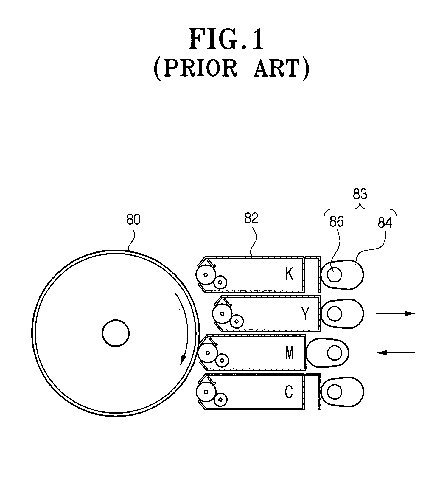
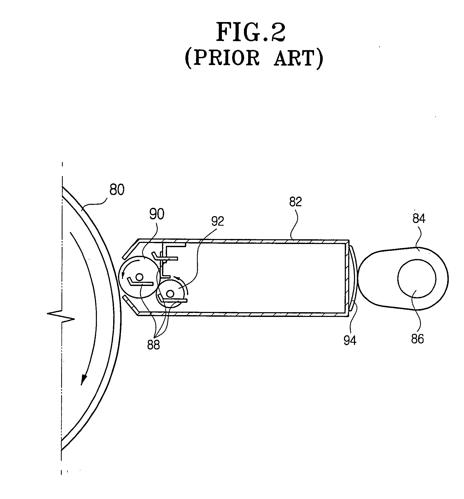
However, the conventional image forming apparatus 10 has a problem of complex construction due to requirement for the eccentric cams 35, 36, 37, 38, cam driving motor (not shown) and the electric clutch for the changing of the developing device among the four developing devices 31, 32, 33, 34.
Additionally, the impact from the contact also causes change of running speed of the photosensitive medium 11, which subsequently causes a degradation of printing quality such as a ‘jitter’.

Method used


Image

  • Apparatus for supplying voltage to developing device
  • Apparatus for supplying voltage to developing device
  • Apparatus for supplying voltage to developing device

Examples


Embodiment Construction

[0059] Reference will now be made in detail to the embodiments of the present invention, examples of which are illustrated in the accompanying drawings, wherein like reference numerals refer to the like elements throughout. The embodiments are described below in order to explain the present invention by referring to the figures.

[0060] In the first aspect of the present invention, the voltage changeover unit is formed of a relay part, and in the second aspect of the present invention, the voltage changeover unit is formed of a solenoid part.

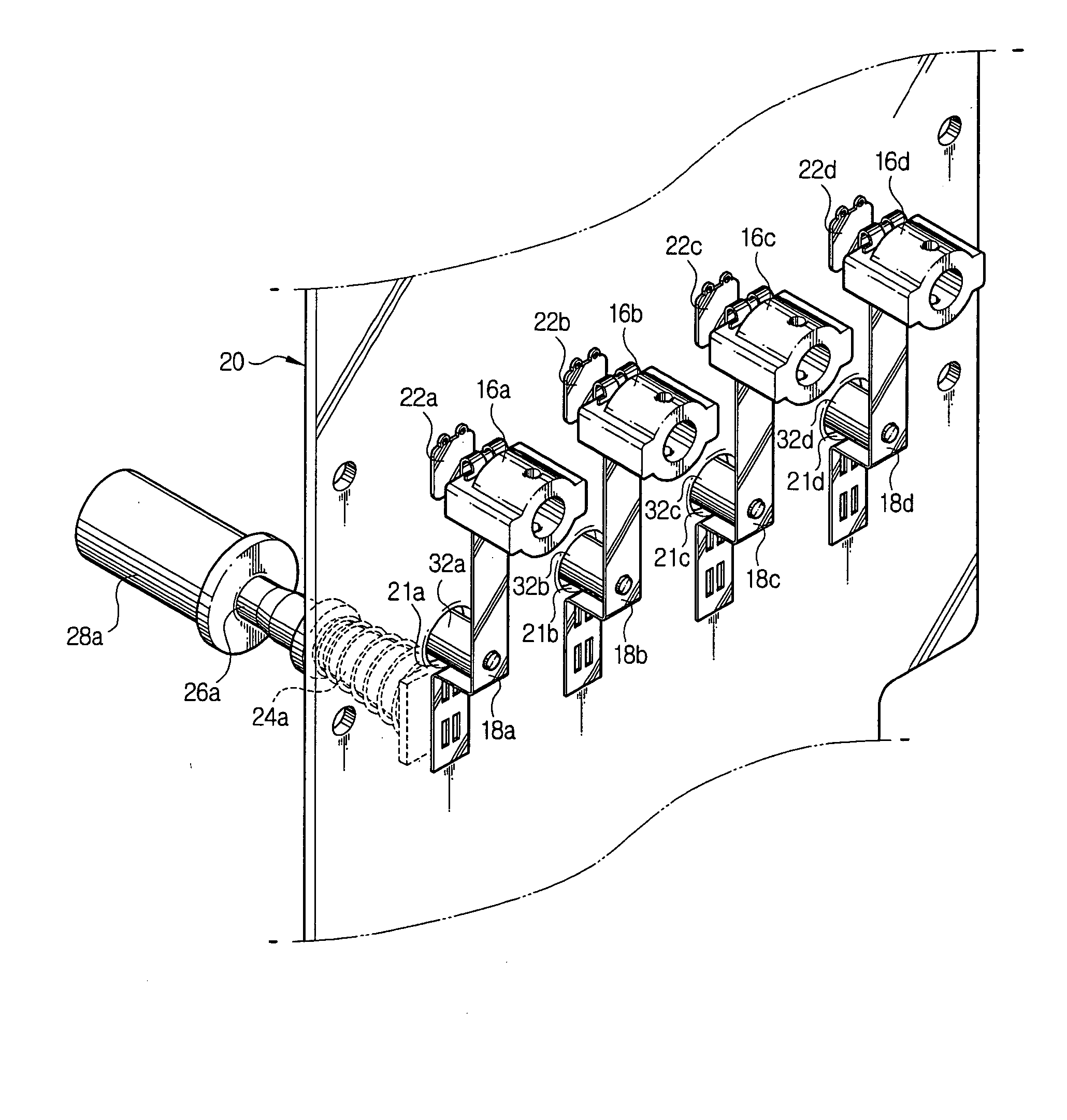
[0061]FIGS. 3 and 4 schematically show a voltage supply device 100 for a developing device according to one aspect of the present invention.

[0062] In the color image forming apparatus having the voltage supply device 100 according to one aspect of the present invention, a photosensitive medium (not shown) and developing devices are provided. The photosensitive medium is in a cylindrical form and for forming an electrostatic latent image thereon...


PUM


Abstract

A voltage supply device for developing devices of a color image forming apparatus has a printed circuit board (PCB) connected with a high voltage supply source, a plurality of fixed contact point terminals provided at one end of the respective color developing devices, and a plurality of voltage changeover units for selectively connecting the PCB and the fixed contact point terminals to selectively supply the voltage from the high voltage supply source to the respective color developing devices. With the voltage supply device, contact point changeover is enabled without having to move the developing device, by using a relay part of a relatively simple structure during the change of developing device. Accordingly, deterioration of printing quality due to shock from the contact with the developing device is avoided, and the reliability of high voltage contact point changeover is improved. Further, the number of high voltage wiring harness, which is required for supplying voltage from the high voltage supply source to the developing devices, can be reduced.

Description

CROSS-REFERENCE TO RELATED APPLICATION [0001] This application claims the benefit of Korean Patent Application No. 2002-59366, filed on Sep. 30, 2002, Korean Patent Application No. 2003-31350 filed on May 16, 2003, and Korean Patent Application No. 2003-39845 filed on Jun. 19, 2003 in the Korean Intellectual Property Office, the disclosure of which is incorporated herein by reference. BACKGROUND OF THE INVENTION [0002] 1. Field of the Invention [0003] The present invention relates to an electrophotographic color image forming apparatus such as color photocopier and a color printer, and more particularly to an apparatus for supplying a high level of voltage to a developing device for a color printing or copying. [0004] 2. Description of the Related Art [0005] As shown in FIG. 1, an electrophotographic color image forming apparatus such as a color laser printer or a color photocopier is generally equipped with a photosensitive medium 11, usually in a drum type, which is continuously r...

Claims


Application Information

Patent Timeline
IPC IPC(8): G03G21/00G03G15/01G03G15/06G03G15/08H01H9/54H01H50/04H01H50/14H01H50/26H01H50/56H01H50/64
CPCG03G2215/0634G03G15/065
Inventor AHN, BYEONG-HWAYOON, YOUNG-MINLEE, SEUNG-YOONLYU, SE-HYUN
Owner S PRINTING SOLUTION CO LTD
Learn More