Multi-cylinder reciprocating compressor

a reciprocating compressor and multi-cylinder technology, applied in the direction of machines/engines, liquid fuel engines, positive displacement liquid engines, etc., can solve the problems of reducing the compression efficiency of the compressor, the valve reed is insufficiently twisted, and the valve reed is difficult to bring the valve reed into satisfactorily close contact with the stopper surface of the retainer, so as to achieve stable opening/closing operation of the valve reed

Inactive Publication Date: 2005-03-10
SANDEN CORP
View PDF0 Cites 2 Cited by
  • Summary
  • Abstract
  • Description
  • Claims
  • Application Information

AI Technical Summary

Benefits of technology

[0012] An object of the present invention is to provide a multi-cylinder reciprocating compressor wherein valve reeds of discharge valves can be reliably twisted when lifted, so as to come into satisfactorily close contact with inclined stopper surfaces of respective retainers, thereby ensuring stable opening / closing operation of the valve reeds.

Problems solved by technology

Since the valve reed has relatively high rigidity against twisting, however, the valve reed is insufficiently twisted when lifted, and it is difficult to bring the valve reed into satisfactorily close contact with the stopper surface of the retainer.
Consequently, the valve reed repeatedly strikes on the stopper surface when lifted, causing vibrations.
Such vibrations not only produce unpleasant noise but impede smooth discharging of the refrigerant from the compression chamber, which lowers the compression efficiency of the compressor.

Method used


Image

  • Multi-cylinder reciprocating compressor
  • Multi-cylinder reciprocating compressor
  • Multi-cylinder reciprocating compressor

Examples


first embodiment

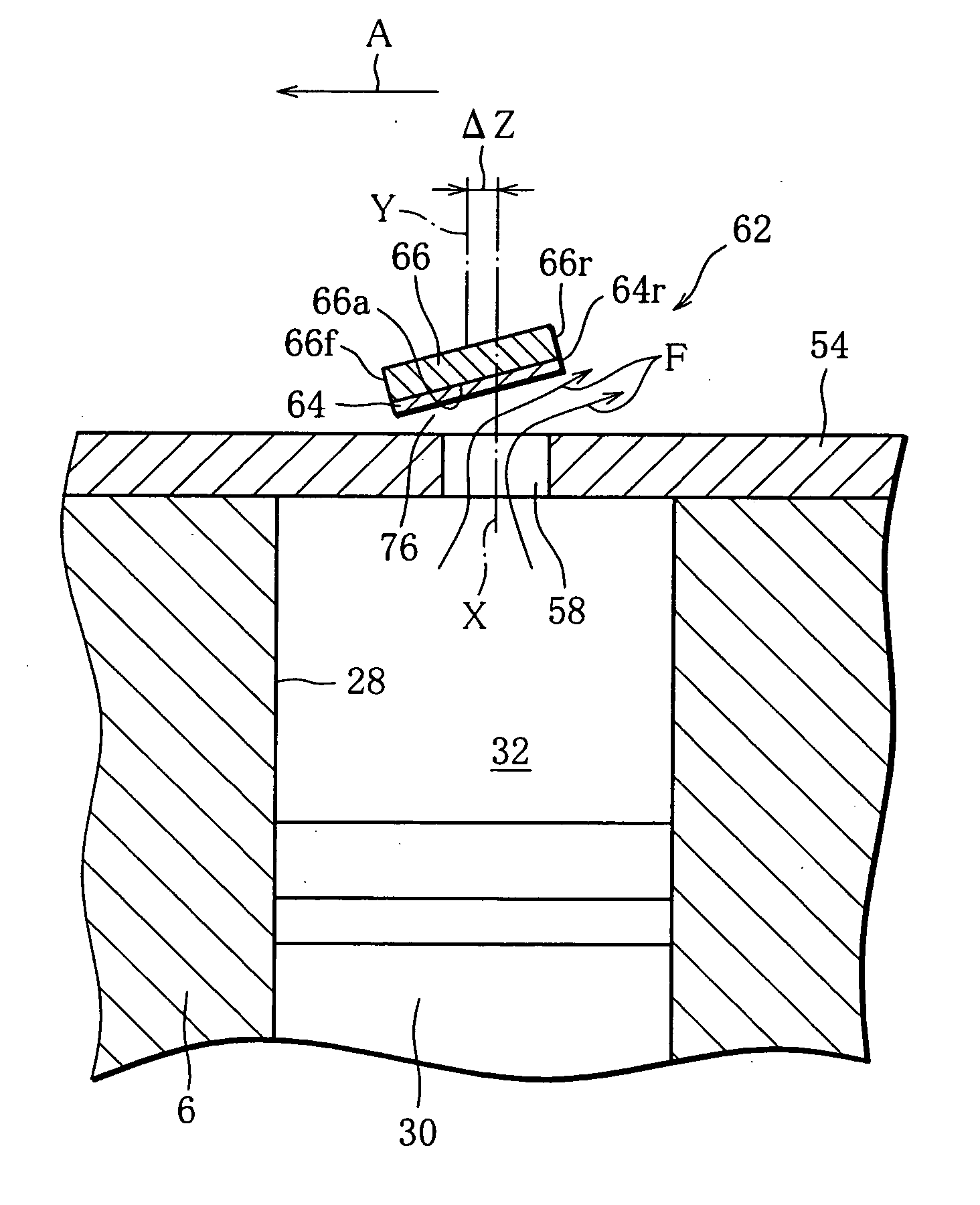
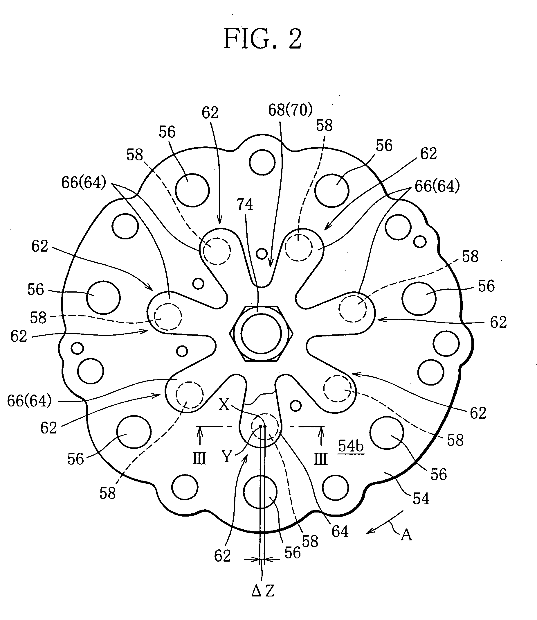
[0054] Each discharge hole 58 and its corresponding discharge valve 62 cooperatively constitute a discharge valve device of the present invention. In the discharge valve device the discharge hole 58 is circular in shape, as clearly shown in FIG. 2. The axis X of the discharge hole 58 (the center of gravity of the cross section of the discharge hole 58) is shifted from the center Y of the valve reed 64 in the width direction thereof by a predetermined distance ΔZ toward the side edge 64r of the valve reed 64 corresponding to the side edge 66r of the retainer 66.

[0055] Accordingly, when the valve reed 64 lifts from the valve plate 54 to open the discharge hole 58 while being elastically deformed by the pressure of the compressed refrigerant in the compression chamber 32, the flow of the refrigerant discharged from the discharge hole 58 collides mainly against one side portion of the valve reed 64 between the center Y in the width direction of the valve reed 64 and the side edge 64r. ...

second embodiment

[0058]FIGS. 4 and 5 illustrate discharge valve devices according to a

[0059] Each discharge valve device of the second embodiment has a discharge hole 78 with a pear-shaped cross section, in place of the discharge hole 58. More specifically, the cross section of the discharge hole 78 has a small-diameter end and a large-diameter end separated from each other in the width direction of the valve reed 64, and the large-diameter end is located on the same side as the side edge 64r of the valve reed 64. Like the discharge hole 58, therefore, the center X of gravity of the cross section of the discharge hole 78 is shifted from the center Y of the valve reed 64 in the width direction thereof by the predetermined distance ΔZ toward the side edge 64r of the valve reed 64.

[0060] Accordingly, when the valve reed 64 is lifted, the flow of the refrigerant discharged from the discharge hole 78 positively applies twisting moment to the valve reed 64 and thereby assists the twisting of the valve re...

third embodiment

[0061]FIG. 6 illustrates discharge valve devices according to a

[0062] Each discharge valve device of the third embodiment has a circular discharge hole 80, like the discharge hole 58, but the axis X (center of gravity) of the discharge hole 80 and the center Y of the valve reed 64 in the width direction thereof are located in a common plane. In the third embodiment, therefore, the flow of the refrigerant discharged from the discharge hole 80 collides uniformly against the distal end portion of the valve reed 64.

[0063] However, in the third embodiment, the valve reed 64 has a bay portion 82 at the side edge 64r thereof. The bay portion 82 is located between the distal end portion and root of the valve reed 64 and decreases the width of the valve reed 64.

[0064] The bay portion 82 of the valve reed 64 serves to displace a twist axis TA of the valve reed 64 from the center Y in the width direction thereof toward the side edge 64f. Accordingly, the axis X of the discharge hole 80 is ev...


PUM


Abstract

A multi-cylinder reciprocating compressor has a plurality of compression chambers and a plurality of discharge valve devices associated with the respective compression chambers. Each discharge valve device includes a valve reed for opening and closing a corresponding discharge hole formed through a valve plate, and a retainer for regulating the lift of the valve reed. The retainer includes a stopper surface inclined with respect to the valve plate as viewed in cross section of the retainer, and the stopper surface has one side edge and the other side edge located remoter from the valve plate than the one side edge. The discharge hole is positioned such that the center of gravity of the cross section thereof is shifted from the center of the valve reed in the width direction thereof toward the other side edge of the stopper surface.

Description

[0001] This nonprovisional application claims priority under 35 U.S.C. 119(a) on Patent Application No. 2003-317977 filed in Japan on Sep. 10, 2003, the entire contents of which are incorporated herein by reference. BACKGROUND OF THE INVENTION [0002] 1. Field of the Invention [0003] The present invention relates to a multi-cylinder reciprocating compressor, and more particularly, to a multi-cylinder reciprocating compressor suitable for use in a refrigeration circuit of an automotive air conditioning system. [0004] 2. Description of the Related Art [0005] This type of multi-cylinder reciprocating compressor is disclosed, for example, in Japanese Utility Model Publication No. H06-25576. The compressor disclosed in this publication has a plurality of compression chambers, a discharge chamber, and discharge valves associated with the respective compression chambers to allow refrigerant compressed in the respective compression chambers to be discharged into the discharge chamber. [0006]...

Claims


Application Information

Patent Timeline
Patent Type & Authority Applications(United States)
IPC IPC(8): F04B27/08F04B27/10F04B39/10
CPCF04B39/1073F04B27/1009Y10T137/7891Y10T137/7892
Inventor ICHIKAWA, YOSHINOBU
Owner SANDEN CORP
Why Eureka
Try Eureka