Battery pack

a battery pack and battery technology, applied in the field of batteries, can solve the problems of difficult mass-manufacture of battery packs at low cost, lead wire or the like disconnection, and high cost of manufacturing this part, and achieve the effect of low cost, strong fastening of output terminals, and simple structur

Inactive Publication Date:
View PDF4 Cites 12 Cited by
  • Summary
  • Abstract
  • Description
  • Claims
  • Application Information

AI Technical Summary

Benefits of technology

[0009] The above battery pack has an advantage that can hold the output terminal at a prescribed position of the molded resin portion with a simple structure, and can provide mass-production of the battery pack at low cost. The reason is that, in the battery pack, the insulating block which is provided with the breaker mechanism is held by being inserted in the molded resin portion which holds a part of or the whole of battery inserted thereto, and the insulating block holds the output terminal on its surface, and the output terminal held by the insulating block is held at the prescribed position so as to be externally exposed from the molded resin portion. The battery pack of this structure has an advantage that can firmly fasten the output terminal by a very simple structure without inserting a terminal board or the like for fastening the output terminal, additionally to an advantage that can manufacture the battery pack by the inserting the insulating block, which is provided with the breaker mechanism, and the battery in the molded resin portion. In the structure that the breaker mechanism and the output terminal are connected to each other in series, there is an advantage that can shorten the connection between the breaker mechanism and the output terminal, in addition, and can simplify the structure. Accordingly, it is possible to provide an excellent electrical property that can discharge a large amount of current while reducing useless power consumption by reduction of internal resistance of the battery pack.
[0010] The insulating block may include a base block and a cover block separately formed of plastic, the cover block being fastened to the base block. This insulating block can fasten the output terminal to the surface of the cover block.

Problems solved by technology

However, since the battery pack of this structure is assembled by inserting the core pack into the external case with effort, it is difficult to mass-manufacture the battery packs at low cost.
However, with the battery pack of this structure, since an output terminal separated from the battery pack is connected through a lead wire, there is a disadvantage that manufactures this part at much expense in time and effort.
In addition, with the battery pack of this structure, there is a disadvantage that disconnection of the lead wire or the like occurs.
However, actually, it is very difficult to mold the molded resin portion with a metal plate as the output terminal temporarily and accurately held at the position in the molding chamber of the mold.

Method used


Image

  • Battery pack
  • Battery pack
  • Battery pack

Examples


Embodiment Construction

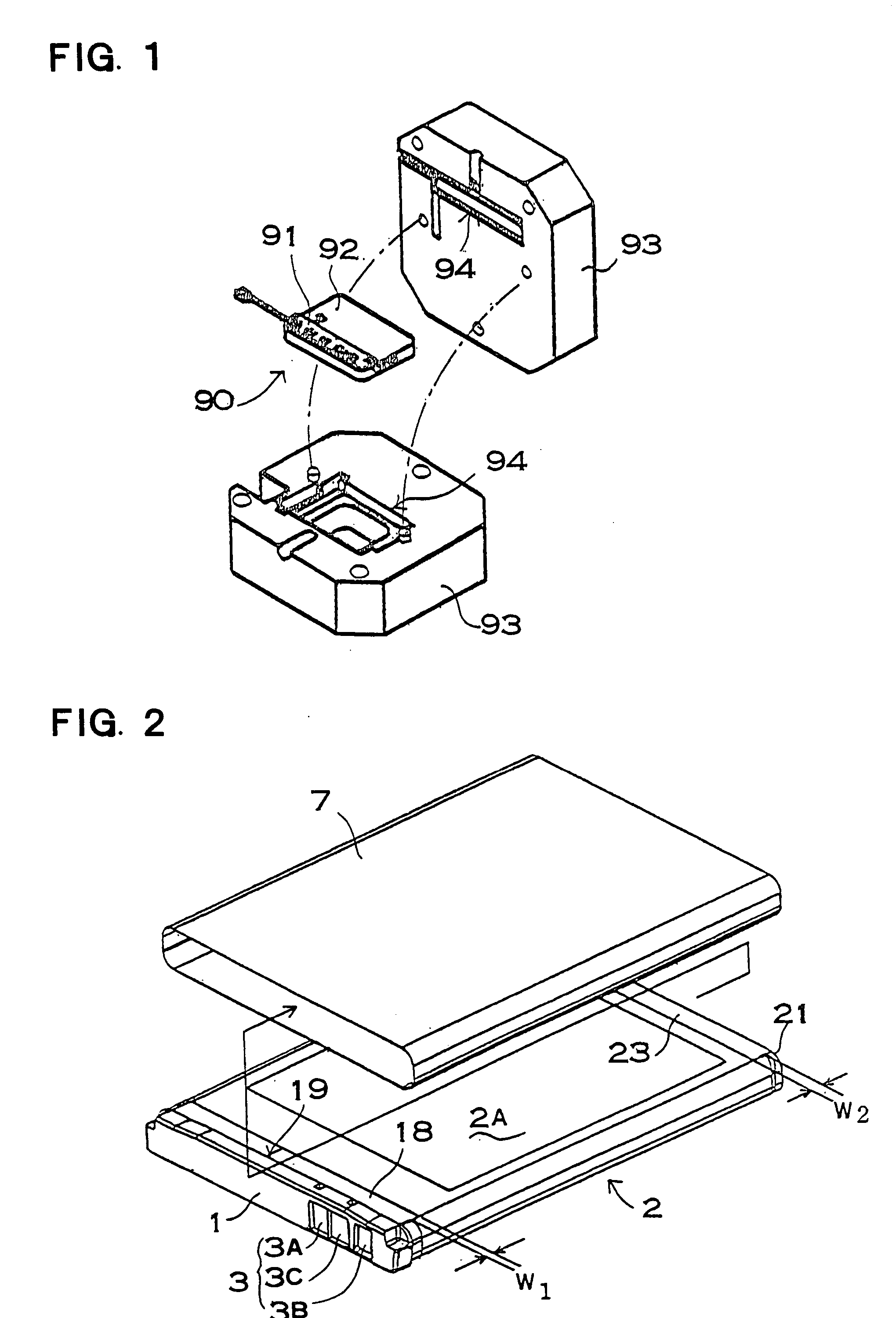
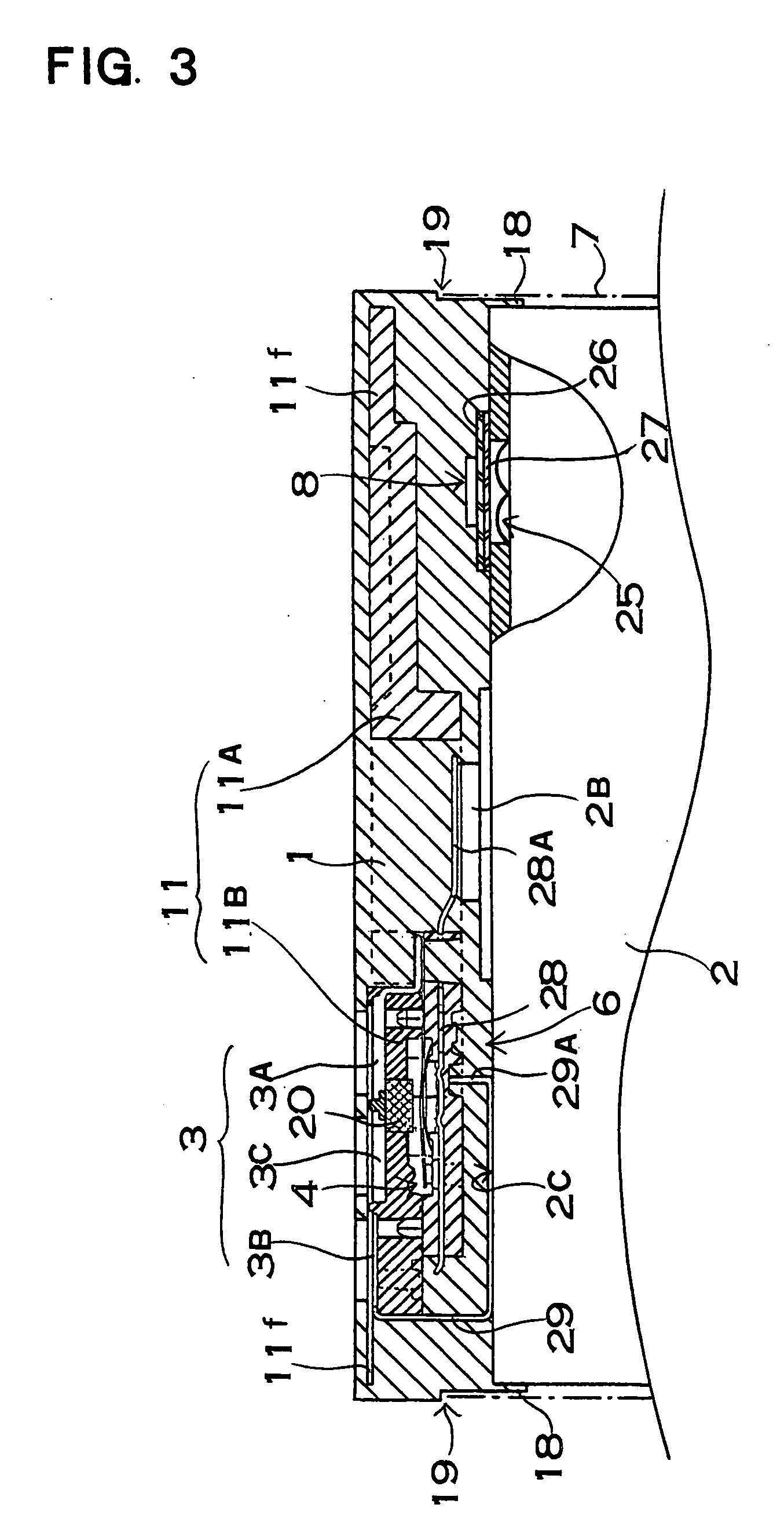
[0047] With a battery pack of FIG. 2, a molded resin portion 1 is molded on a battery end surface of a thin battery. When molded, this molded resin portion 1 fastens an insulating block 11 inserted thereto as shown in a cross-sectional view of FIG. 3. Although the molded resin portion 1 is fastened onto a terminal end surface where a protrudent terminal 2B is provided in the battery pack of the figure, the insulating block may be inserted into a molded resin portion which is fastened onto a battery end surface opposite to the battery end surface where the protrudent terminal is provided. In the thin battery, though is not illustrated, the insulating block may be inserted into a molded resin portion which is fastened onto one of both narrow side surfaces. With the battery pack of the case where the insulating block inserted to the side opposite to the protrudent terminal, or of the case where the insulating block is to the side surface of the thin battery, a lead member of the insula...


PUM

PropertyMeasurementUnit
timeaaaaaaaaaa
timeaaaaaaaaaa
thicknessaaaaaaaaaa

Abstract

A battery pack comprises a molded resin portion which holds a part of or the whole of battery inserted thereto, and an externally exposed output terminal. The battery pack further comprises an insulating block which is provided with a breaker mechanism for cutting-off current flow when an over-current flows. The insulating block is held by being inserted in the molded resin portion. The insulating block holds the output terminal on its surface. The output terminal held by the insulating block is held at a prescribed position so as to be externally exposed from the molded resin portion.

Description

BACKGROUND OF THE INVENTION [0001] The present invention relates to a battery pack manufactured by inserting a part or the whole of a battery into a molded resin portion. [0002] High dimensional accuracy is required for a battery pack. Particularly, high dimensional accuracy is required for the position of an output terminal. The reason is that the output terminal is accurately set to an attachment portion provided in electrical equipment to be connected to a power supply terminal of the electrical equipment so that poor contact does not occur. Currently, a commercially available battery pack has a structure in which a core pack with parts necessary for a battery connected thereto is inserted in an external case formed of plastic. With the battery pack of this structure, forming the external case in an accurate dimension can form the battery pack in prescribed outer dimensions. However, since the battery pack of this structure is assembled by inserting the core pack into the externa...

Claims


Application Information

Patent Timeline
Patent Type & Authority Applications(United States)
IPC IPC(8): H01M6/50H01M10/42H01M50/583
CPCH01M2/1061H01M2/34H01M2200/106H01M10/425H01M2/348Y02E60/10H01M50/581H01M50/583H01M50/20
Inventor WATANABE, ATSUSHITAMAI, MIKITAKATERAOKA, HIROKINAKA, MASATSUGU
Why Eureka
Try Eureka