Flame arrester

a technology of arrester and flame, which is applied in the direction of boring tools, steam boiler components, combustion process, etc., can solve the problems of increased cost, increased cost, and continual burning of the emergent face of the arrester, and achieves the effects of simple, durable, and easy assembly

Inactive Publication Date: 2005-03-10
ALHAMAD SHAIKH GHALEB MOHAMMAD YASSIN
View PDF4 Cites 18 Cited by
  • Summary
  • Abstract
  • Description
  • Claims
  • Application Information

AI Technical Summary

Benefits of technology

[0013] This invention is based on the discovery that a flame can be prevented from flashing back in an upstream direction through a stream of flammable gas by placing in the stream an arrester comprising a contained layer or layers of nested ellipsoids formed from expanded metal sheets produced from a magnesium foil. It has been found that the expanded metal net magnesium alloy ellipsoids not only arrest the upstream travel of the flame but also withstand the extreme heat of the flame and survive any shock wave that may be associated with the ignition of the flame.
[0014] The product of the present invention therefore is a flame arrester adapted for placement in a stream of flammable atmosphere for preventing an external flame at a downstream point in the stream from flashing back in an upstream direction to the source of the flammable atmosphere, said arrester comprising a contained layer of nested ellipsoids formed from expanded metal sheets made from magnesium alloy foil.
[0015] In one embodiment hereinafter described the flame arrester is placed in the vent pipe of a storage tank for a flammable substance. In another embodiment, the arrester is located in a conduit of a closed combustion system. In a further embodiment, the arrester is used to prevent the pilot or burner light of a hot water heater or space heater from igniting a fugitive flammable atmosphere caused by the accidental spillage of fuel in the vicinity of the heater.

Problems solved by technology
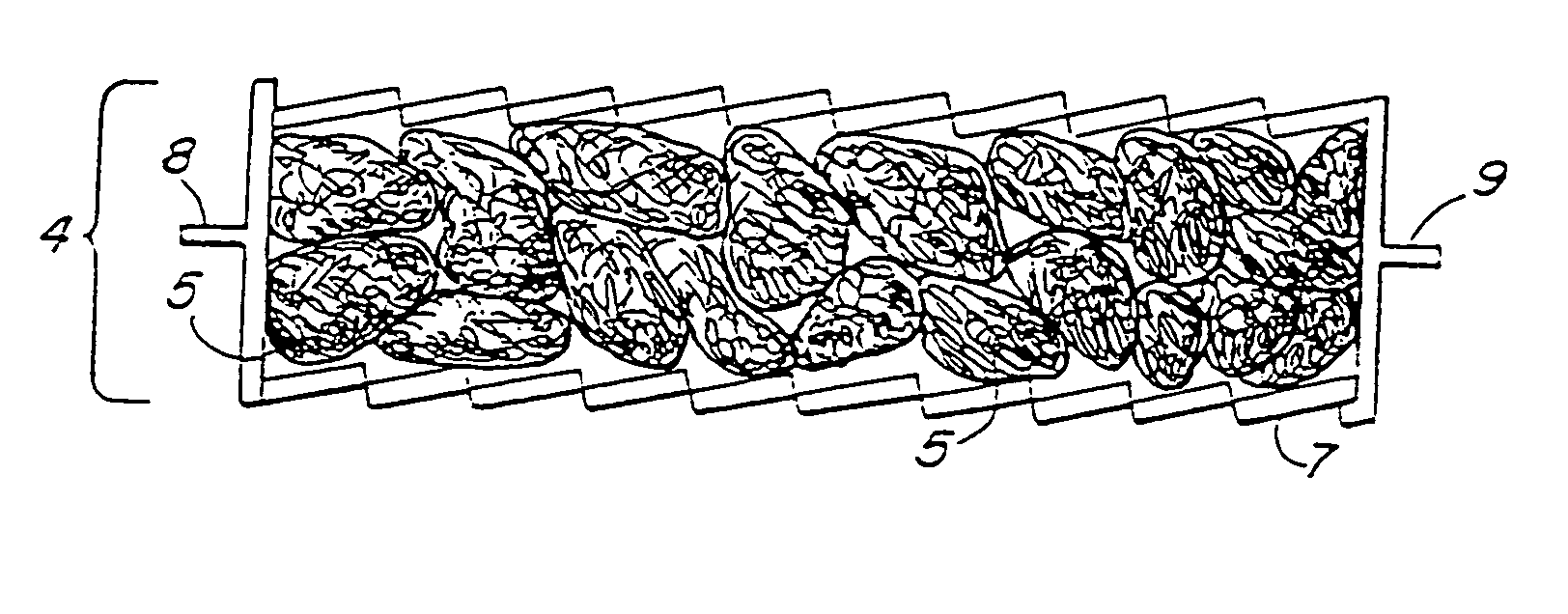
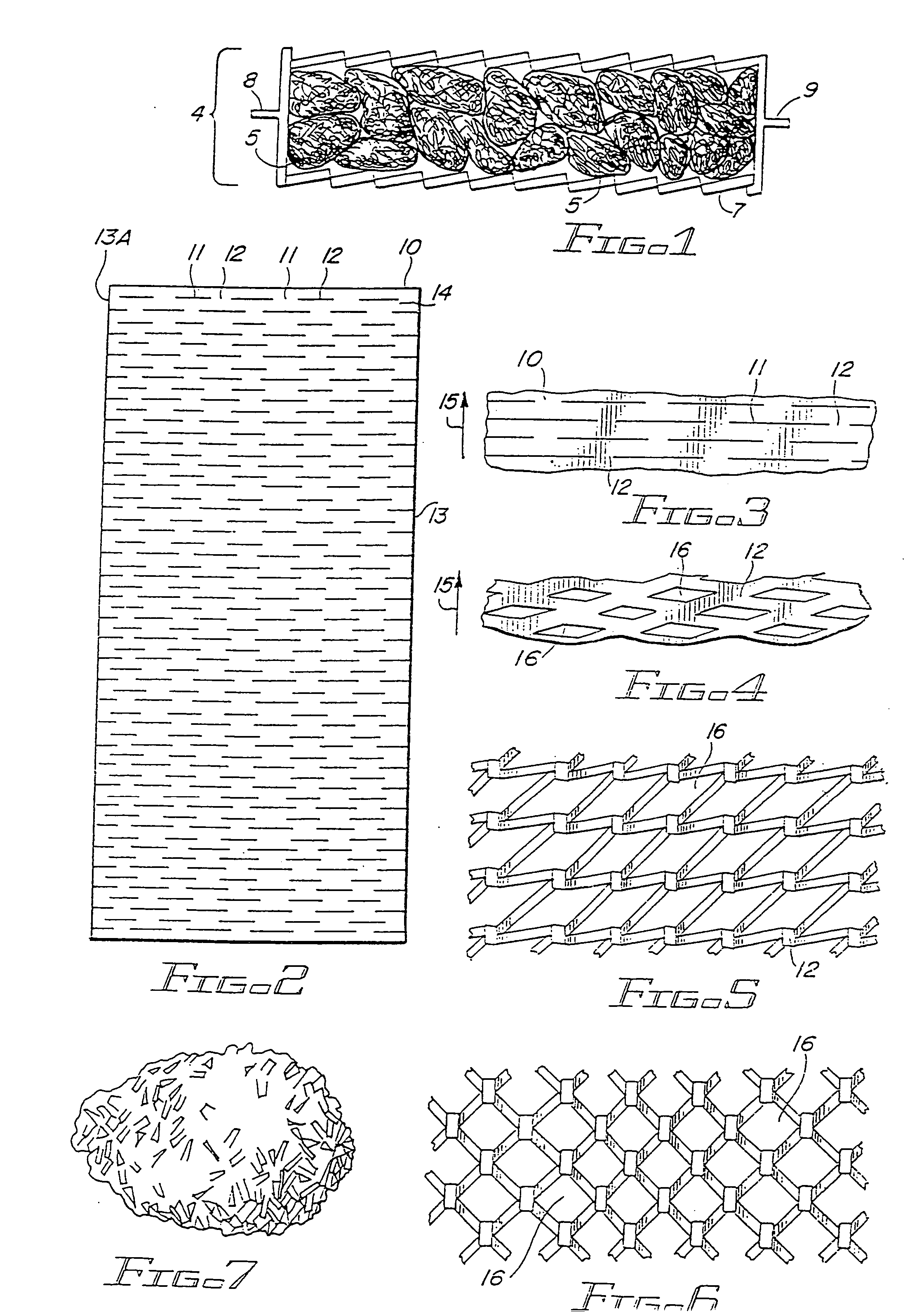
If such a flashback is not prevented, the reservoir of flammable material would ignite, resulting in a destructive fire or explosion.
A difficulty which is commonly encountered is that most open-structured configurations which possess the required internal passage dimensions for successfully arresting a flame are able to survive the heat of the flame for only a limited time.
When unwanted ignition takes place, there is normally a continued burning on the emergent face of the arrester over a relatively long period of time while the source of burning vapors is still present.
Such extended exposure to the high temperature of the flame is normally destructive of the arrester, and therefore it is common practice to provide mechanical or other means responsive to the temperature of the arrester for closing a valve or otherwise shutting off the source of burning vapors.
However, the need for the mechanical or other means introduces additional expense, constant service and maintenance, and an additional array of moving parts which can malfunction.
A further difficulty is that, under certain ignition or detonation conditions, a rapidly developing shock wave will precede the flame front and can damage or completely destroy the open-structured configurations of the flame arrester elements before they have an opportunity to perform their flame arresting function.

Method used


Image

  • Flame arrester
  • Flame arrester
  • Flame arrester

Examples


example 1

Description of Baseline Test—Without the Flame Arrester of the Present Invention

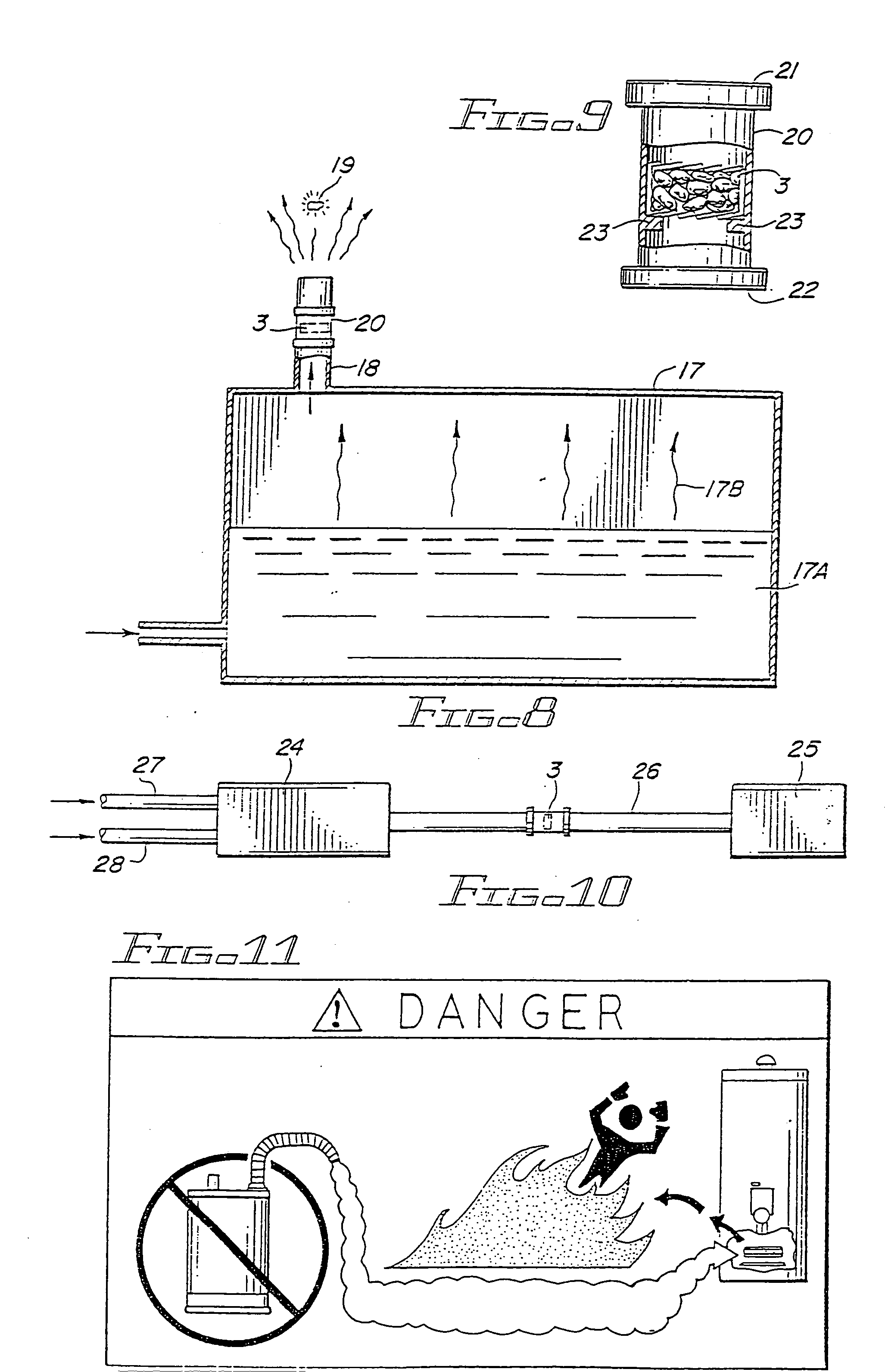
[0048] The residential water heater 29 utilized in this demonstration is shown in FIGS. 12 and 13. The heater had the following specifications: [0049] Bottom-fired: natural gas, 33,000 Btu / hour [0050] Standing pilot: natural gas, 1,000 Btu / hour [0051] Burner: steel, multi-port, ring configuration [0052] Water tank capacity: 30 gallons [0053] Vent: central, 3-inch vertical flue [0054] Cabinet style: “tall”, 60 inches

[0055] The tank 29 included the standard components such as a main burner 30, a burner access panel 31, and a vertical flue vent 32. Positioned beneath the water heater 29 was a stainless steel moat 33, into which regular octane gasoline was poured to simulate an accidental spill. The natural gas supply line (not shown) was made of copper tubing to withstand the flames that resulted when the spill was ignited. Baseline tests consisted of exposing the as-received, water-filled, and operating ...


PUM

PropertyMeasurementUnit
diameteraaaaaaaaaa
diameteraaaaaaaaaa
thicknessaaaaaaaaaa

Abstract

A highly efficient flame arrester adapted for use in preventing an external flame from backflashing upstream in a pipe, or a conduit, or a stream carrying a flammable substance. The flame arrester comprises a contained layer of nested ellipsoids formed from expanded metal sheets made from magnesium alloy foil. The arrester is useful in fuel tanks, combustion systems, sea-going tankers, hot water or space heaters, and the like.

Description

[0001] This application is a continuation of pending application Serial No. 825,644, filed Apr. 3, 2001, which was a continuation of application Serial No. 603,608, filed Jun. 26, 2001 (now U.S. Pat. No. 6,216,791), which was a division of application Serial No. 133,471, filed Aug. 13, 1998 (now U.S. Pat. No. 6,105,676), which was a continuation-in-part of pending application Serial No. 789,509, filed Jan. 27, 1997 (now U.S. Pat. No. 5,794,707, which was a continuation of application Serial No. 695,537, filed Aug. 12, 1996 (now abandoned), which was a continuation of application Serial No. 226,954, filed Apr. 13, 1994 (now abandoned).BACKGROUND AND PRIOR ART [0002] The present invention relates to a flame arrester or firecheck device that is adapted to prevent a backfire from traveling upstream through a stream of flammable gas, and thus prevent unwanted fire or explosion that might otherwise be caused by the backfire. [0003] A flame arrester is a passive device that permits the flo...

Claims


Application Information

Patent Timeline
Patent Type & Authority Applications(United States)
IPC IPC(8): A62C3/06B21D31/04B65D25/38F23D14/82
CPCA62C3/06A62C4/02F23M2900/11021B65D25/385F23D14/82B21D31/04
Inventor ALHAMAD, SHAIKH GHALEB MOHAMMAD YASSIN
Owner ALHAMAD SHAIKH GHALEB MOHAMMAD YASSIN
Why Eureka
Try Eureka