Patch antenna integrated in a wristwatch

a wristwatch and antenna technology, applied in the field of patch antennas in wristwatches, can solve the problems of affecting the reliability of operation, and affecting the robustness of the antenna structure, so as to achieve the effect of simple, inexpensive and reliabl

Active Publication Date: 2005-03-10
THE SWATCH GRP RES & DEVELONMENT LTD
View PDF5 Cites 28 Cited by
  • Summary
  • Abstract
  • Description
  • Claims
  • Application Information

AI Technical Summary

Benefits of technology

[0008] It is thus a general object of the present invention to provide a solution which assures a sealed connection between the antenna elements external and internal to the middle part of the watch in a simple, inexpensive and reliable manner, without thereby prejudicing the aesthetic appearance of the assembly, while ensuring that this wristwatch assembly, and the antenna integrated therein, is robust.

Problems solved by technology

One solution, which would consist in forming these connections respectively via back cover 5 of the case and via bezel 10, both metallic, requires, however, either passing through insulating case 2, which makes manufacturing considerably more complex and expensive, or leaving electric conductors visible, which is undesirable, particularly from an aesthetic point of view.
It will also be noted that such a dipole antenna integrated in the wristband requires the use, at least for the radiating element, of a conductor 6 of sinuous shape with a determined unfolded length dependant on the desired wavelength corresponding to the central frequency of the signal to be received, which may, depending upon the desired reception frequency, raise problems regarding the robustness of the antenna structure and thus operating reliability over time.

Method used


Image

  • Patch antenna integrated in a wristwatch
  • Patch antenna integrated in a wristwatch
  • Patch antenna integrated in a wristwatch

Examples


first embodiment

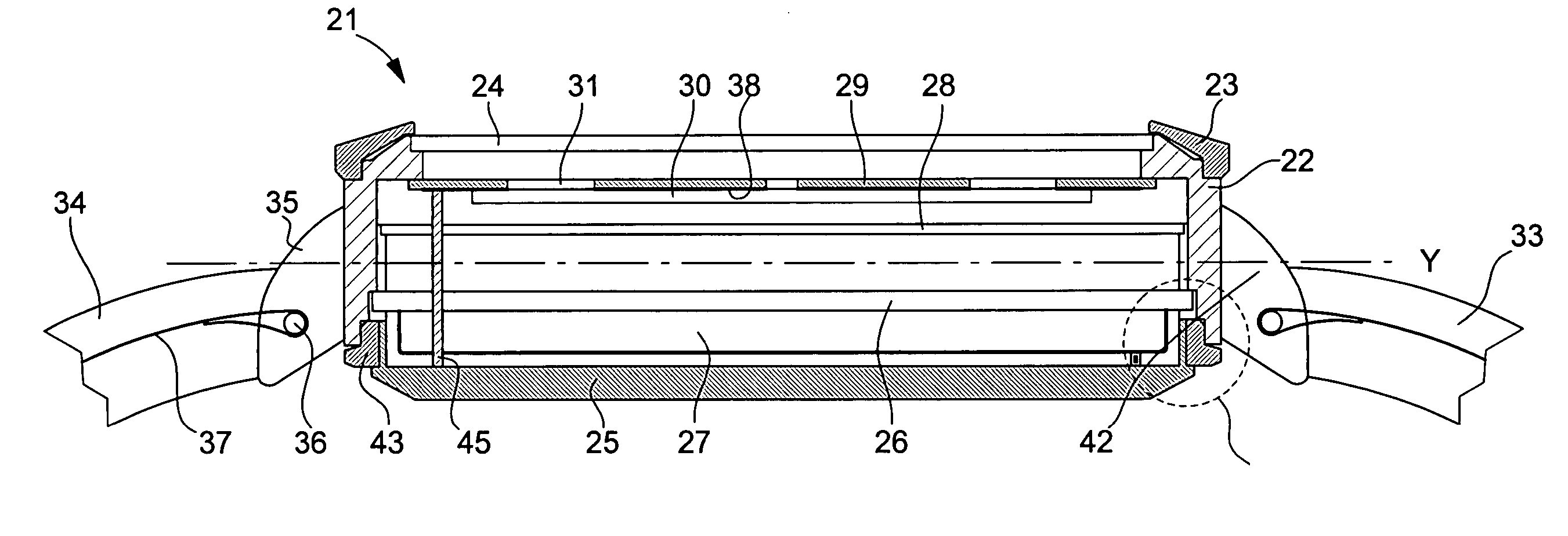
[0023] First of all, by way of non-limiting example, reference will be made to FIG. 2 showing a schematic cross-section of a wristwatch according to the invention.

[0024] Watch 21, as shown, includes a metal middle part 22, able to made in a single piece with or separately from a bezel 23, middle part 22 defining a middle plane Y of the watch. Watch 21 is closed at the top by means of a glass 24 supported by middle part 22 and fixed in a sealed manner, for example, by being driven into a material, for example, made of Hytrel, forming a gasket. Within the scope of this first embodiment, the watch is closed at the bottom by means of a metal back cover 25, insulated from middle part 22 via a gasket 43, preferably made of a malleable plastic, for example Hytrel. An enlarged view of the zone in dotted lines is given in FIG. 4.

[0025] Inside the watch are shown the printed circuit 26, supporting the radio-frequency module 27, the printed circuit clock 28 to which the watch movement (not sh...

second embodiment

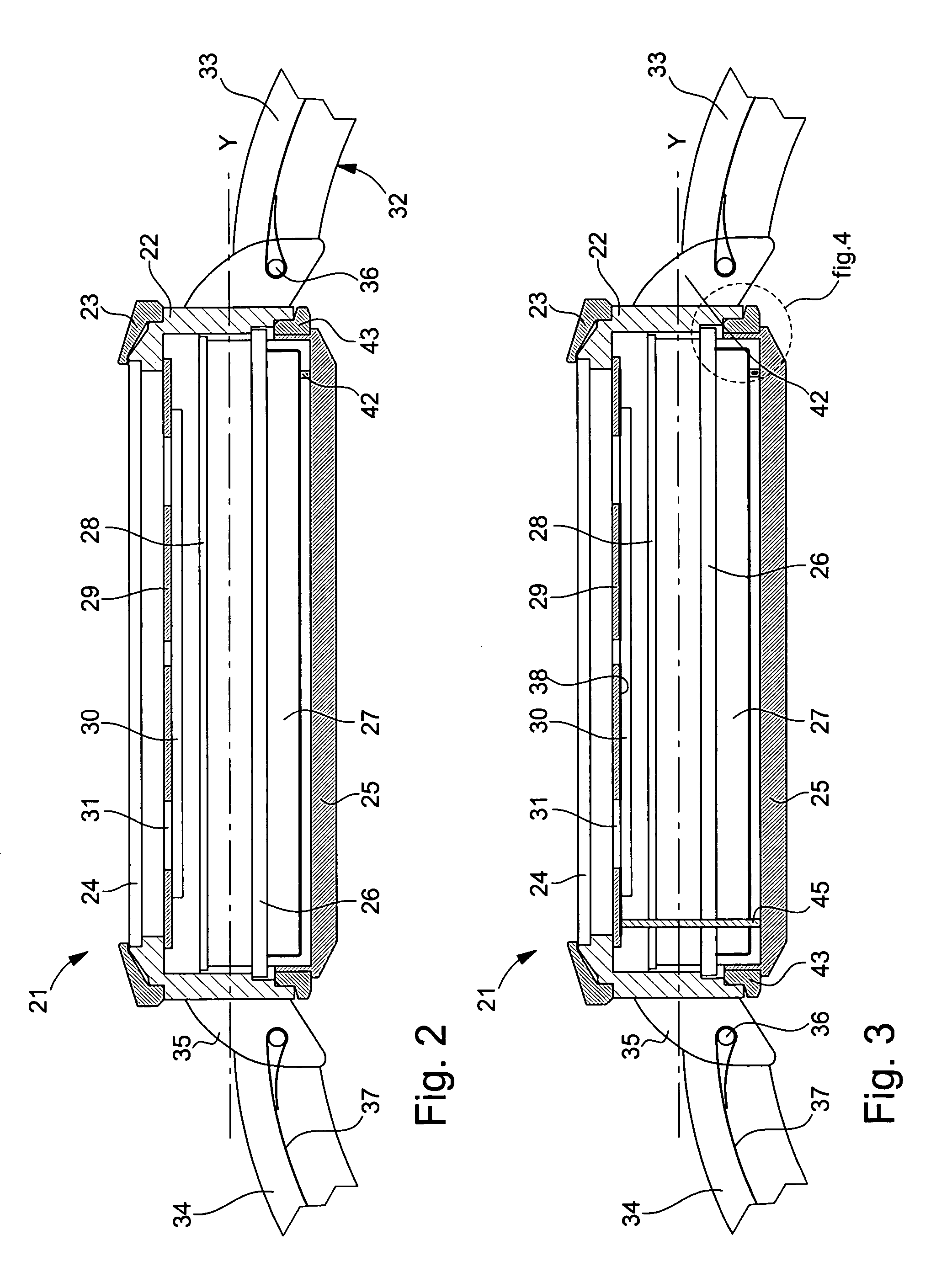
[0030] Secondly, also by way of example, reference will be made to FIG. 3, showing a schematic cross-section of a wristwatch according to the invention.

[0031] This second embodiment differs from the first embodiment presented hereinbefore, essentially as regards the structure used for making the radiating element of the antenna. Indeed, it has been demonstrated within the scope of the present invention that the radiating element has better features, particularly reception features, with a cylindrical radiating structure. Thus, in order to obtain said radiating cylinder, the radiating element includes two conductive surface elements, each being arranged in a substantially parallel plane to the middle plane defined by middle part 22.

[0032] According to this second embodiment, the two surface elements are formed, on the one hand, by metal back cover 25 and, on the other hand, by a metal layer 38 applied over a part of the non visible face of dial 29, so as not to be in contact with mi...


PUM


Abstract

There is disclosed a wristwatch (21) including a middle part (22) defining a middle plane (Y), conductive means (35, 36) for attaching the wristband (32) to the middle part, a radio-frequency module (27) arranged inside the middle part and connected, on the one hand, to a ground plane and, on the other hand, to a radiating element, insulated from each other and forming an antenna. The ground plane includes at least one conductive surface portion (37) of the wristband connected to the wristband attaching means and the middle part which is conductive, the latter being connected from the inside to the radio-frequency module. The radiating element includes a first conductive surface element (25) arranged in a substantially parallel plane to the middle plane defined by the middle part.

Description

[0001] This application claims priority from European Patent Application No. 03019977.2 filed Sep. 3, 2003, the entire disclosure of which is incorporated herein by reference. FIELD OF THE INVENTION [0002] The present invention concerns generally the integration of an antenna in a wristwatch, and more specifically, the arrangement in the wristwatch of the ground plane and the radiating element, these two elements forming an antenna. [0003] The antenna can be used, in particular, for receiving and / or transmitting radio-electric signals, which are transmitted to a radio-frequency module integrated in the watch. BACKGROUND OF THE INVENTION [0004] A wristband antenna for a radio-electric receiver integrated in a watch is known from in the prior art, particularly from EP Patent No. 0 308 935. As is shown schematically in FIGS. 1A and 1B, watch 1 is formed of a case 2 containing radio-electric receiver 3 and a wristband 4. The back cover of the case includes a first metal part 5, which fo...

Claims


Application Information

Patent Timeline
Patent Type & Authority Applications(United States)
IPC IPC(8): G04B37/16G04G17/08G04G21/04G04R60/04H01Q1/27H01Q1/44
CPCG04G21/04G04R60/04H01Q1/273
Inventor CASAGRANDE, ARNAUDOESCH, YVES
Owner THE SWATCH GRP RES & DEVELONMENT LTD
Why Eureka
Try Eureka