Filament wound strut and method of making same

a technology of filament wounds and struts, which is applied in the direction of shock absorbers, other domestic objects, mechanical apparatus, etc., can solve the problems of composite materials that are not adapted to react to such loads, struts may be frequently required to transmit both tension and other problems, to achieve the effect of high reaction efficiency

Inactive Publication Date: 2005-03-17
JONES BRIAN
View PDF0 Cites 15 Cited by
  • Summary
  • Abstract
  • Description
  • Claims
  • Application Information

AI Technical Summary

Benefits of technology

[0010] It is, therefore, one of the primary objects of the present invention to provide a filament wound strut which is highly effective in reacting to both tension and compression loads and which also reacts both shear and edge bearing modes of force.
[0013] It is another object of the present invention to provide a method of making a filament wound strut and which is made in such manner that it will effectively transfer loads and react both tension loads and compression loads.
[0014] It is also an object of the present invention to provide a method of making a filament wound strut in such manner that load which is transferred into the composite avoids unfavorable edge bearing and shear modes of force transfer.
[0015] It is an additional object of the present invention to provide a method of manufacture of a filament wound strut having the desired axial stiffness through axially oriented fibers and the required strength in the fork or lug sections thereof to readily transmit shear and edge bearing loading.
[0016] The present invention generally provides a strut which can be used in a wide variety of load transmitting applications, and which is formed of filamentary material arranged in such manner that it can be used in a variety of such load transmitting applications and which is made in a relatively inexpensive and minimal labor involved process.
[0018] The present invention relates in broad terms to both a filament wound strut capable of effectively reacting to a variety of load conditions, as well as a method of making the strut. The filament wound strut may preferably, although not necessarily, have a cylindrically shaped elongate section with relatively flat ends tapering into the elongate section. The ends are specially constructed so as to have relatively flat opposed surfaces, such as upper and lower surfaces, with a quasi-isotropic pre-form incorporated therein and with filament type reinforcement wound around the periphery thereof in a racetrack type arrangement. This construction is highly effective in that the winding will react to tension loads, and the inner laminate reacts to compression loads. Moreover, the laminate is constructed so that it will reduce the effects of load transfer through edge bearing and shear.

Problems solved by technology

One of the significant problems which arises in the use of filament containing struts is the fact that the struts may be frequently required to transmit both tension loads and compression loads.
If loads of this type are transmitted into a composite strut through an edge bearing or otherwise a shear mode, the composite material is not adapted for reacting to such loads.
The composite material is highly effective in tension loads but not in compression and edge bearing loads and in shear loads.
Consequently, and while filament reinforced composite struts can be highly effective in a variety of applications, they are limited, to some extent, by their ability to react both compression and shear modes of loading.
However, none of this prior art has provided any effective means of producing a strut which is capable of reacting to shear loading and to edge bearing loading.
Consequently and heretofore, there has not been any effective filament wound strut or any method of making same which is capable of reacting to both of these loads as well as transmitting tension loads.

Method used


Image

  • Filament wound strut and method of making same
  • Filament wound strut and method of making same
  • Filament wound strut and method of making same

Examples


Embodiment Construction

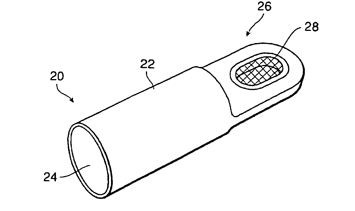
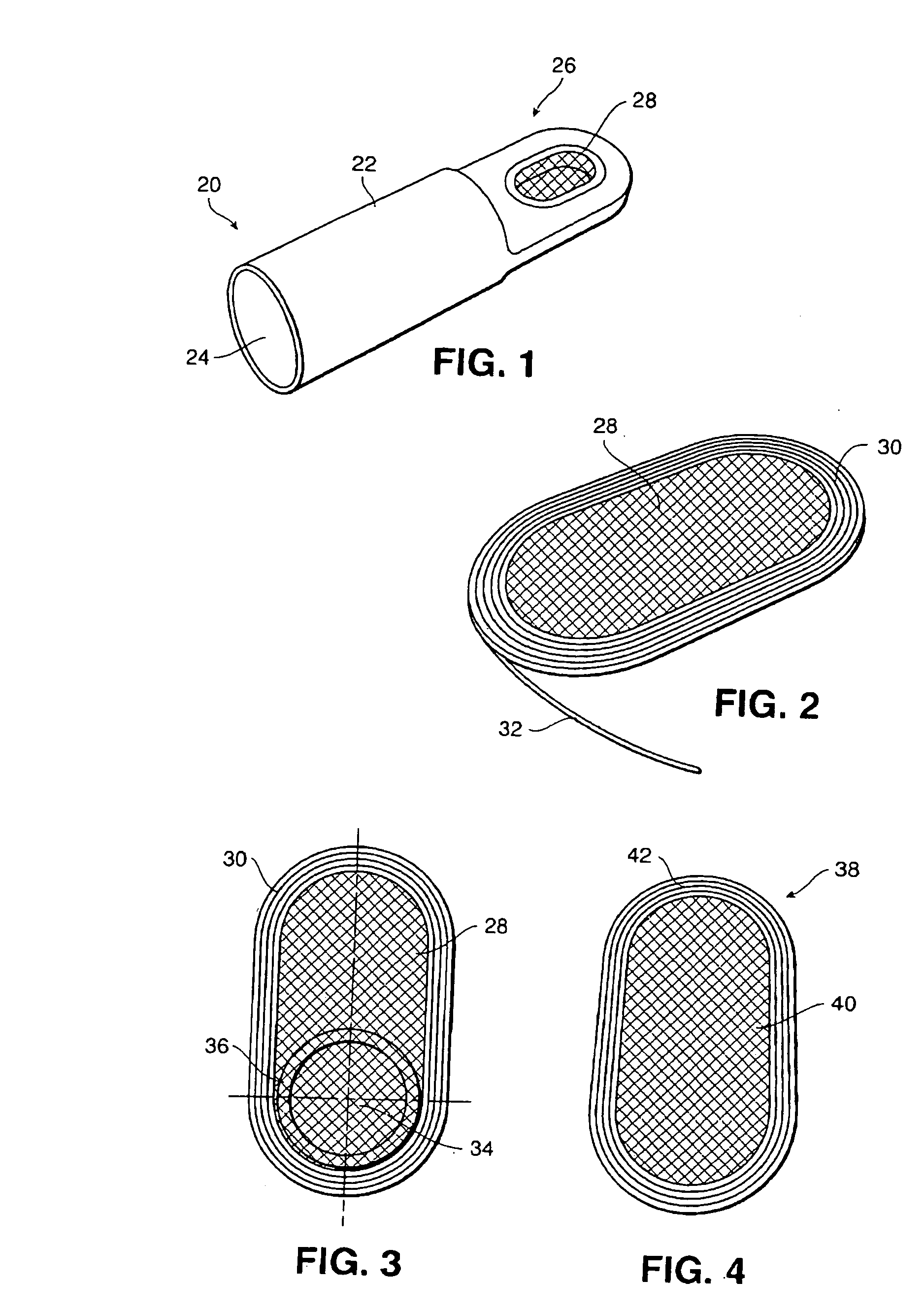
[0036] Referring now in more detail and by reference characters to the drawings, 20 designates one form of strut which may be constructed in accordance with the present invention and includes a cylindrically shaped body 22 as best shown in FIG. 1. In this particular embodiment, the body 22 is shown as being hollow having an interior bore 24. However, in many cases, the cylindrical body 22 will be of solid cross-section.

[0037] The body 22 is primarily formed of filament wound material. Generally, the body can be formed of any reinforced composite material and can be actually formed in any conventional filament winding operation. The mandrel used in the winding process may become in-situ and remain in the strut as produced. Exemplary of the filament reinforcement are filaments of carbon, glass, boron and the like. Moreover, the filaments can be cured in either a thermosetting resin or a thermoplastic resin. A well known number of thermosetting and thermoplastic resins are available f...


PUM

PropertyMeasurementUnit
tensionaaaaaaaaaa
shapeaaaaaaaaaa
lengthaaaaaaaaaa

Abstract

A filament wound strut as well as a method of making the strut. The filament wound strut has a cylindrical section merging into ends through tapered end sections and which ends may be forked or otherwise arranged to receive a lug fitting. The flat ends may be provided with a specially designed pre-form having a generally oval shape, and which is formed by filament reinforcement in a racetrack format surrounding a quasi-isotropic laminate. In accordance with this construction, the wound structure will react to tension loads and the inner laminate reacts to compression loads, while minimizing the load transfer through edge bearing and shear. A method of producing the strut is also provided in which filament materials are wound about a mandrel with proper winding pattern and sufficient thickness to produce the desired axial stiffness and the required strength in each of the end sections. Thereafter, the material may be consolidated and polymerized in an autoclave.

Description

RELATED APPLICATIONS [0001] This application is based on and claims for priority, the filing date of my co-pending U.S. Provisional Patent application Ser. No. 60 / 489,538, filed Jul. 22, 2003. BACKGROUND OF THE INVENTION [0002] 1. Field of the Invention [0003] This invention relates in general to certain new and useful improvements in filament wound struts as well as a method of making same and, more particularly, to filament wound struts constructed in such manner that they are effective in reacting to tension loads as well as to compression loads in such manner to minimize transfer of such loads into the composite material through edge bearing and shear modes. [0004] 2. Brief Description of Related Art [0005] Struts are used to absorb shock and carry loads in a wide variety of equipment and in a variety of applications. Exemplary thereof is the use of struts in aircraft allowing for movement of wing flaps, tail flaps and the like. Struts are also used in aircraft, particularly in ...

Claims


Application Information

Patent Timeline
Patent Type & Authority Applications(United States)
IPC IPC(8): B29C53/58F16C7/00F16F1/366F16F9/00
CPCB29C33/76B29C53/564B29C53/58B29C53/821B29D99/0046F16F2236/06B29L2031/06B29L2031/7096F16C7/026F16F1/366F16F2236/04B29K2105/08
Inventor JONES, BRIAN
Owner JONES BRIAN
Why Eureka
Try Eureka