
Automated process and apparatus for planarization of topographical surfaces

a topographical surface and automatic process technology, applied in the direction of hollow wall articles, other domestic articles, coatings, etc., can solve the problems of affecting the final yield or performance of the device, the non-planar surface is no longer suitable for constructing the next structural layer, and the non-planar surface cannot be replanarized. , to achieve the effect of high planarization ratio and quick and efficient planarization of various coated substrates

Inactive Publication Date: 2005-03-17
BREWER SCI
View PDF38 Cites 35 Cited by
  • Summary
  • Abstract
  • Description
  • Claims
  • Application Information

AI Technical Summary

Benefits of technology

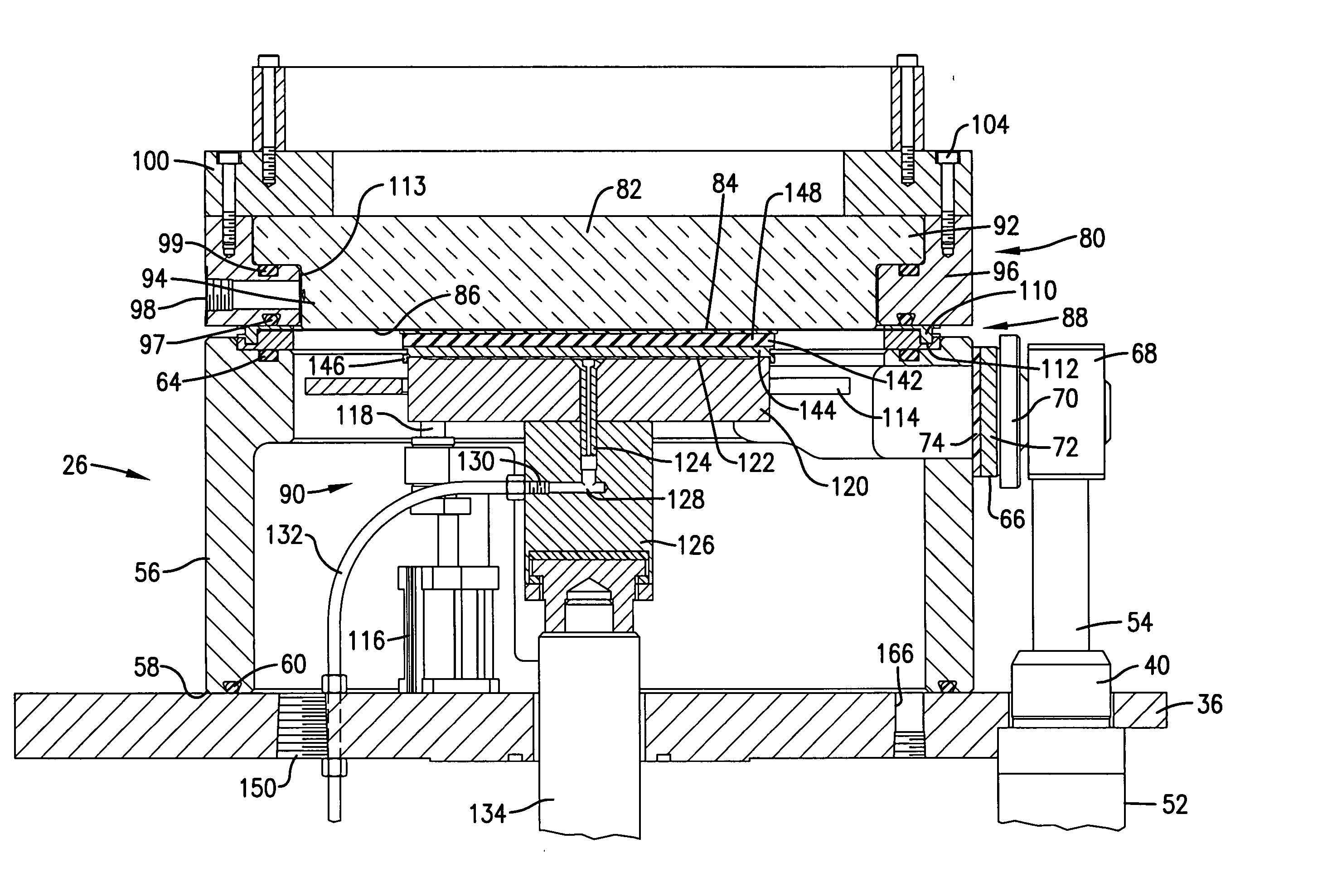
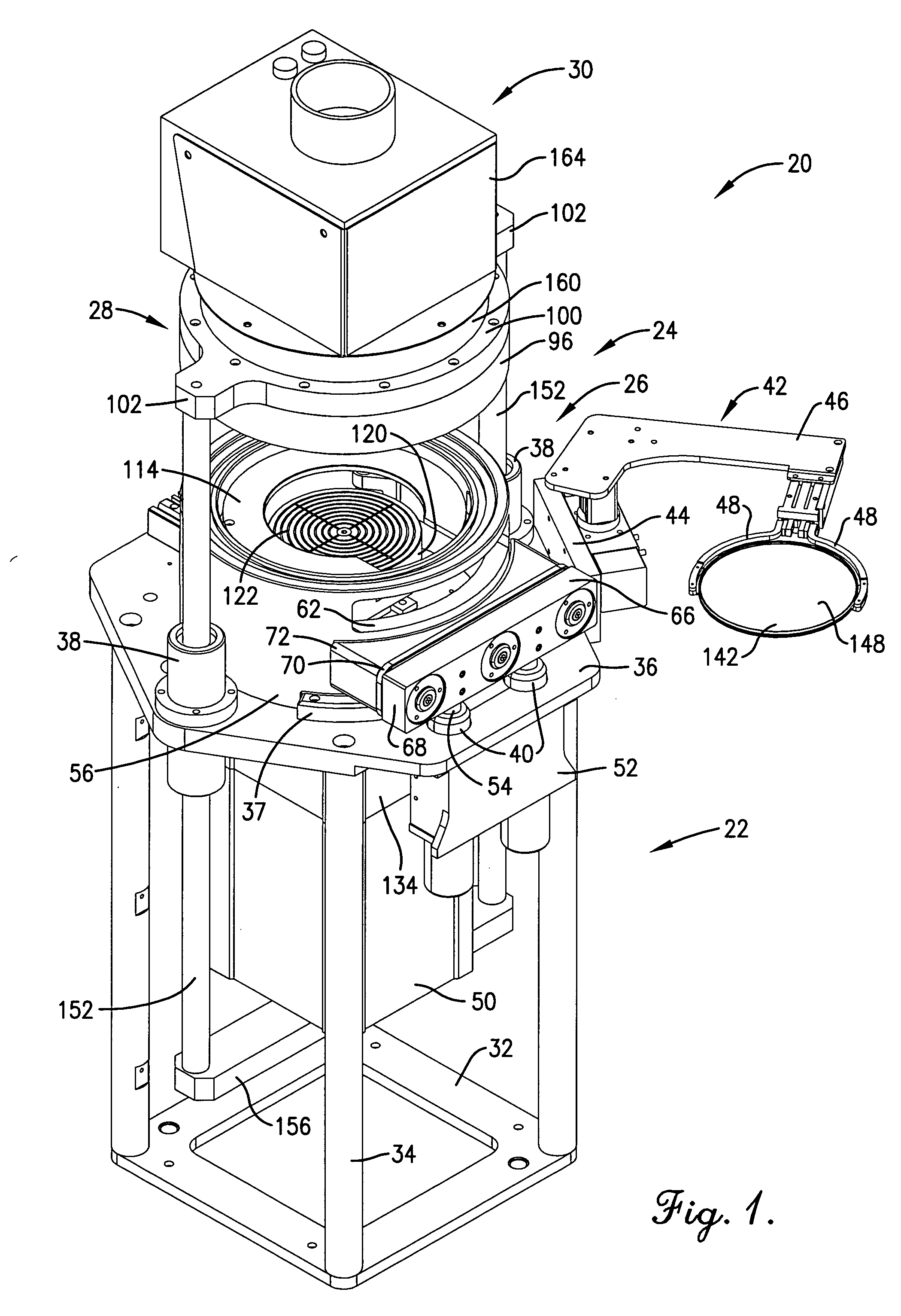
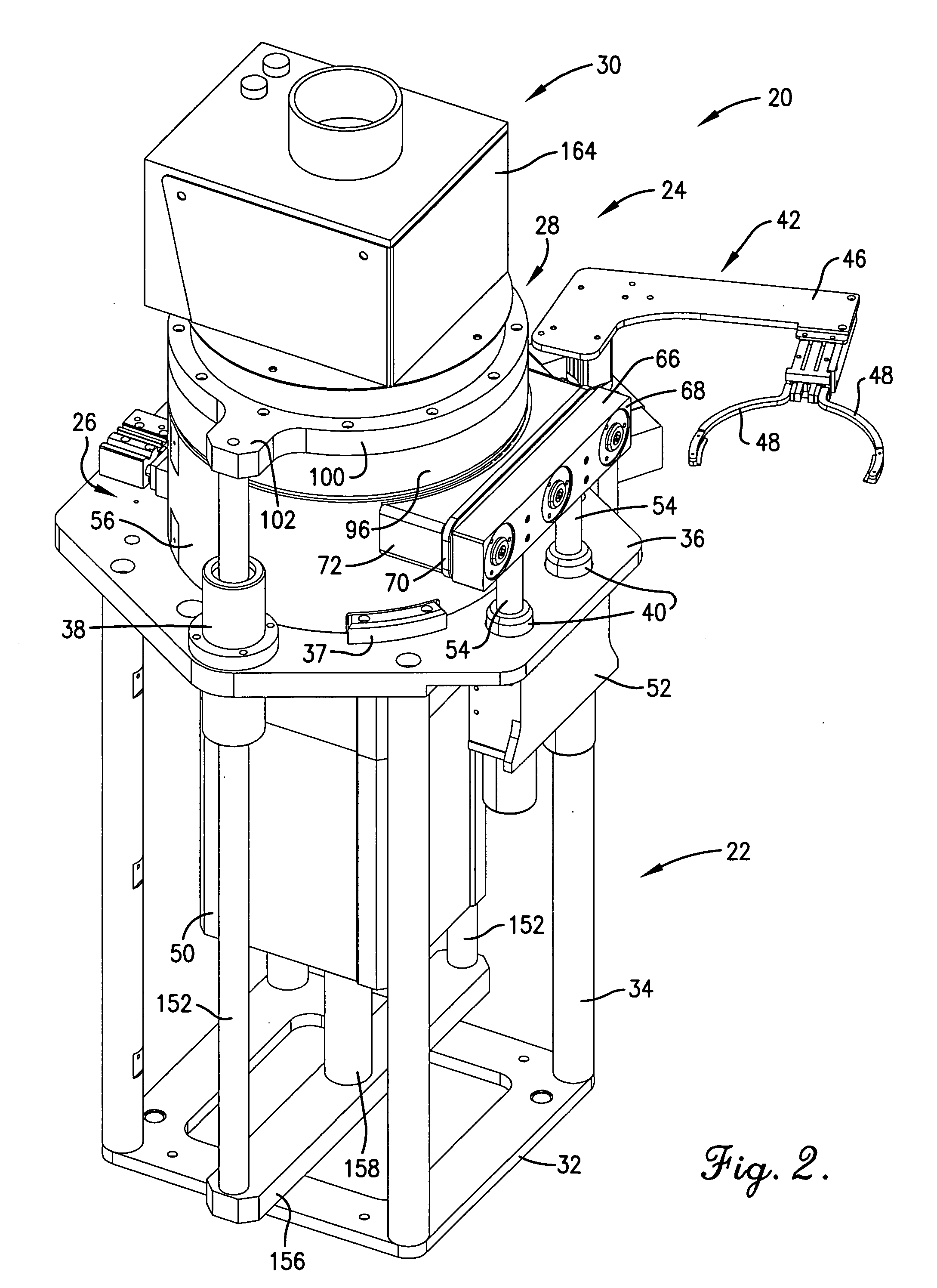
[0016] The present invention overcomes the problems outlined above and provides improved contact planarizing apparatus and corresponding methods, which are capable of quickly and efficiently planarizing various coated substrates, while achieving very high planarization ratios. Broadly speaking, the apparatus of the invention includes a support operable to engage and hold a thin flexible sheet of material (which is preferably an optically flat material fabricated from Teflon, other fluorocarbon polymers, or silicones) with an assembly operable to support and hold a substrate with the coating thereof proximal to the sheet. A differential pressure assembly is also provided to create a pressure differential across the sheet of sufficient magnitude to deflect the sheet so that the latter contacts the central region of the surface of the coating, but is spaced from the periphery thereof. The support assembly is also shiftable for moving the substrate into face-to-face planarizing contact with the sheet throughout substantially the entirety of the surface area of the coating. Finally, the apparatus includes a device for curing the coating during the course of such full planarizing contact.

Problems solved by technology

However, if the surface is not planar, that is, it has topographic features, materials may not coat with a uniform thickness, which may greatly affect the final yield or performance of the device.
The non-planar surface is no longer suitable for constructing the next structural layer.
However, a longer plasma etch time is needed to etch the thicker films.
The Prybyla patent does not provide the details associated with reducing the technology to practice.
This patent also fails to include the process for separating the coated wafer from the optical flat surface and the optimal range of process parameters to perform contact planarization fully automated.

Method used


Image

  • Automated process and apparatus for planarization of topographical surfaces
  • Automated process and apparatus for planarization of topographical surfaces
  • Automated process and apparatus for planarization of topographical surfaces

Examples


example i

[0064] In this example, a trench wafer having a photocurable material was planarized using apparatus 20. In particular, a silicon wafer having trench structures about 1 μm was used as the substrate. The featured density of the wafer ranged from about 4-96%. A photocurable material was prepared by thoroughly mixing 20 grams of epoxy (D.E.R. 354LV, Dow Chemical Co.), 80 grams of propylene glycol monomethyl ether (PGME, Aldrich Chemical Co.), and 1.2 grams of Sarcat KI-85 (Sartomer Chemical) in a yellow-lighted laboratory. The material was then filtered using a 0.2 μm filter and stored in a clean brown bottle. A film of the photocurable planarization material less than 0.5 μm thickness was spin-coated onto the silicon trench wafer.

[0065] During processing, the closed apparatus chamber was evacuated to less than 20 torr for about 30 seconds to remove residual solvent. During planarization, the substrate was pressed against the Teflon optical flat surface using a force of about 68 psi f...

example ii

[0067] In this example a thermocurable material was applied to a silicon wafer. The wafer was prepared by first coating it with a silicon dioxide film having a thickness of about 1 μm. A pattern containing vias of 0.2 to 1 μm in diameter and having various feature density areas was patterned into the silicon dioxide film. The depth of the vias was about 1 μm. A thermocurable material was prepared as set forth in Example I, except that 1.0 grams of Nacure® Super XC-A 230 catalyst (King Industries) was used in lieu of the Sarcat product. The material was spin-coated to a thickness of about 0.2 μm onto the silicon via wafer.

[0068] The coated wafer was transferred to the apparatus 20 which, after sealing, was evacuated to less than about 20 torr for about 180 seconds to remove residual solvent. The coated substrate was pressed against the optical flat surface using a force of 68 psi for 60 seconds. during this time a pulsing UV / infrared heating light was illuminated through the optical...

example iii

[0070] In this example, photocurable planarization material consisting of 5 grams of Novolac epoxy resin (D.E.R.™ 354LV, The Dow Chemical Company), 5 grams of t-butyl glycidyl ether (Aldrich), and 0.6 grams of 50% triarylsulfonium hexafluorophosphate (a photo acid generator) solution (Aldrich) was formulated and mixed thoroughly. The solvent used in the photo acid generator solution was a reactive solvent. The material was filtered with 0.2 μm filter.

[0071] A 1.7 μm thick layer of the planarization material was coated onto a 6-inch silicon wafer surface that had been treated with an adhesion promoter APX-K1 (Brewer Science, Inc.) using the vendor's recommended process. A standard edge bead removal process was conducted that removed about 5 mm of edge bead.

[0072] The substrate was placed within the apparatus 20 as described in previous examples, and pressed against the optical flat surface using a pressure of 68 psi for 30 seconds. During this contact, a continuous UV light from a ...


PUM

PropertyMeasurementUnit
pressureaaaaaaaaaa
pressureaaaaaaaaaa
thicknessaaaaaaaaaa

Abstract

An improved apparatus (20) and method are provided for effective, high speed contact planarization of coated curable substrates such as microelectronic devices to achieve very high degrees of planarization. The apparatus (20) includes a planarizing unit (28) preferably having an optical flat flexible sheet (88) and a backup optical flat body (82), and a curing assembly (30). In operation, a substrate (78) having a planarizable coating (76) is placed within a vacuum chamber (26) beneath sheet (88) and body (82). A pressure differential is created across sheet (88) so as to deflect the sheet into contact with a central region C of the coating (76), whereupon the coating (76) is brought into full planarizing contact with sheet (88) and body (82) by means of a support (114) and vacuum chuck (120); at this point the coating (76) is cured using assembly (30). After curing, a pressure differential is established across sheet (88) for sequentially separating the sheet from the peripheral portion P of the coating, and then full separation of the sheet (88) and coating (76).

Description

CROSS REFERENCED TO RELATED APPLICATION [0001] This application claims the benefit of provisional application Ser. No. 60 / 486,021 filed Jul. 10, 2003. This provisional application is incorporated by reference herein.[0002] This invention was made with the U.S. Government support under ATP #70NANB1H3019 awarded by the National Institute of Standards and Technology (NIST). The Government has certain rights in the invention.BACKGROUND OF THE INVENTION [0003] 1. Field of the Invention [0004] The present invention is broadly concerned with the improved methods and apparatus for the contact planarization of surfaces such as those developed during the manufacture of advanced integrated circuit and other devices. More particularly, the invention is concerned with such methods and apparatus wherein a coated substrate is placed adjacent an optical flat flexible sheet, and the latter is first deflected to contact a central region of the coating, followed by full, pressurized planarizing contac...

Claims


Application Information

Patent Timeline
Patent Type & Authority Applications(United States)
IPC IPC(8): B29C35/08B29C41/02B29C59/00
CPCH01L21/31058H01L21/6719H01L21/67092
Inventor MCCUTCHEON, JEREMY W.
Owner BREWER SCI
Learn More