Injection device for light metal injection molding machine

Active Publication Date: 2005-03-17
SODICK CO LTD
View PDF5 Cites 15 Cited by
  • Summary
  • Abstract
  • Description
  • Claims
  • Application Information

AI Technical Summary

Benefits of technology

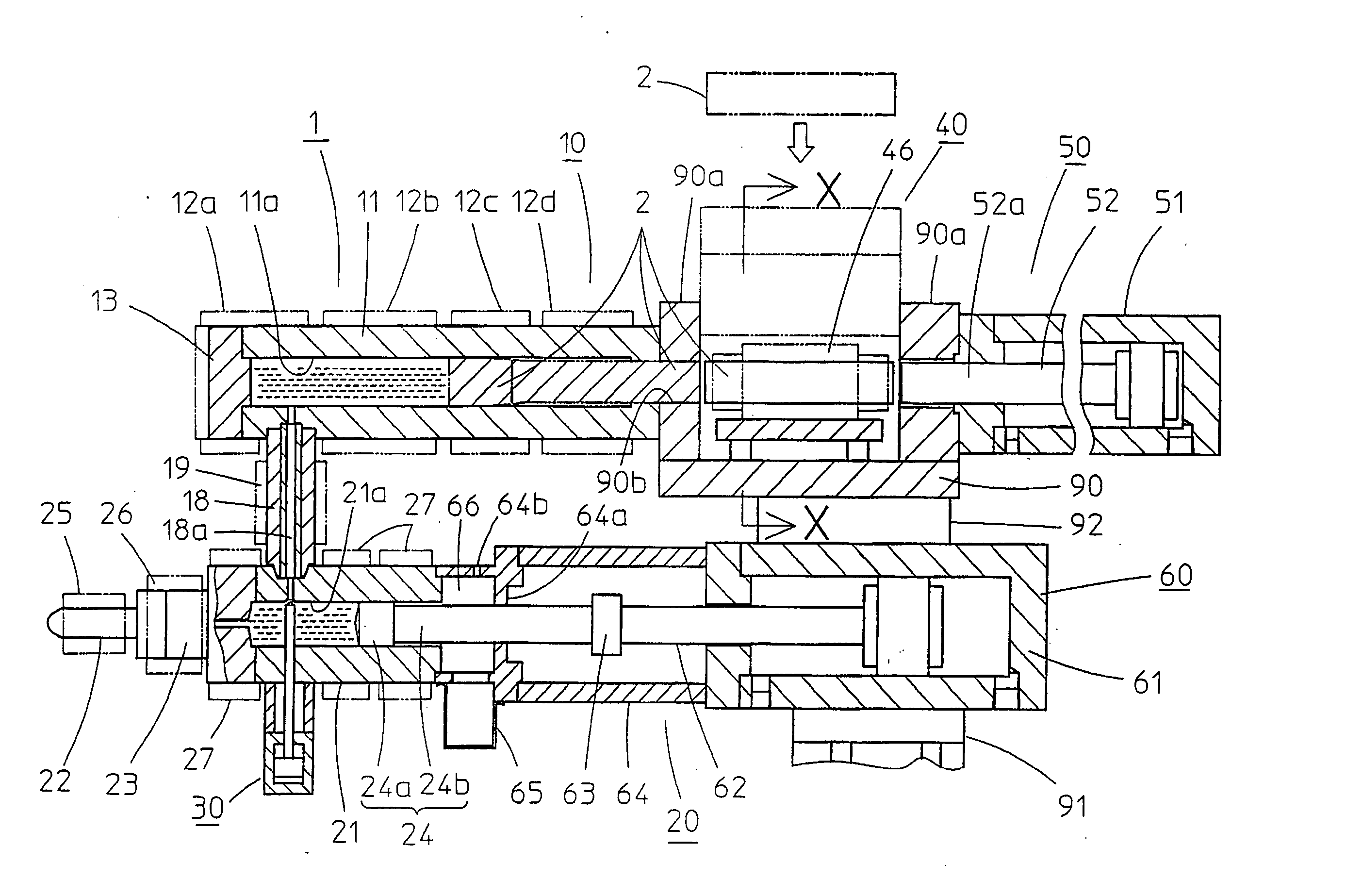
[0027] Using the above structure, it is naturally possible to rapidly purge air and gas remaining inside the melting cylinder and the injection cylinder at the time of commencing operation. As such, it is possible to remedy a problem where molten metal fl

Problems solved by technology

However, with the above-described molding methods, there is a problem with the following improvements.
First of all, with the die casting method, since a large capacity furnace is used the unit accompanies increase in scale, and since a lot of molten metal is kept at a high temperature the unit results in increased running costs.
Also, because it takes a long time to raise the temperature of the furnace, maintenance of the furnace takes at least a day.
This sludge also causes wear.
On the other hand, with the thixotropic molding, melting of the pellet-shaped material is carried out by rotating a screw, which means that it is not always easy to consistently melt the material to a desired semi-molten state.
Also, since the molding material is a pellet-shaped material causing an

Method used


Image

  • Injection device for light metal injection molding machine
  • Injection device for light metal injection molding machine
  • Injection device for light metal injection molding machine

Examples


first embodiment

[0069] As for the melting device 10 of a first embodiment, a cylinder bore 11a of a melting cylinder 11, except for a base end section, comprises a cylinder bore 11b having a diameter a few mm larger than the billet 2, and has a stepped section 11c formed at the base end, as shown in FIG. 3. The size of this larger diameter cylinder bore 11b is determined in advance in accordance with the material and size of the molded item, and in the case of a molding device for molding magnesium alloy, for example, is selected so that a gap with respect to the billet 2 is from 0.5 to 2 mm, and is preferably about 1 mm. Also, the position of the stepped section 11c is determined in advance and is related to the required volume of molten metal and the temperature setting of the heater 12d, or the gap between the larger diameter cylinder bore 11b and the billet 2. The heaters 12a to 12d are the same as those already described.

[0070] With this type of structure, when the billet 2 is pushed forwards ...

second embodiment

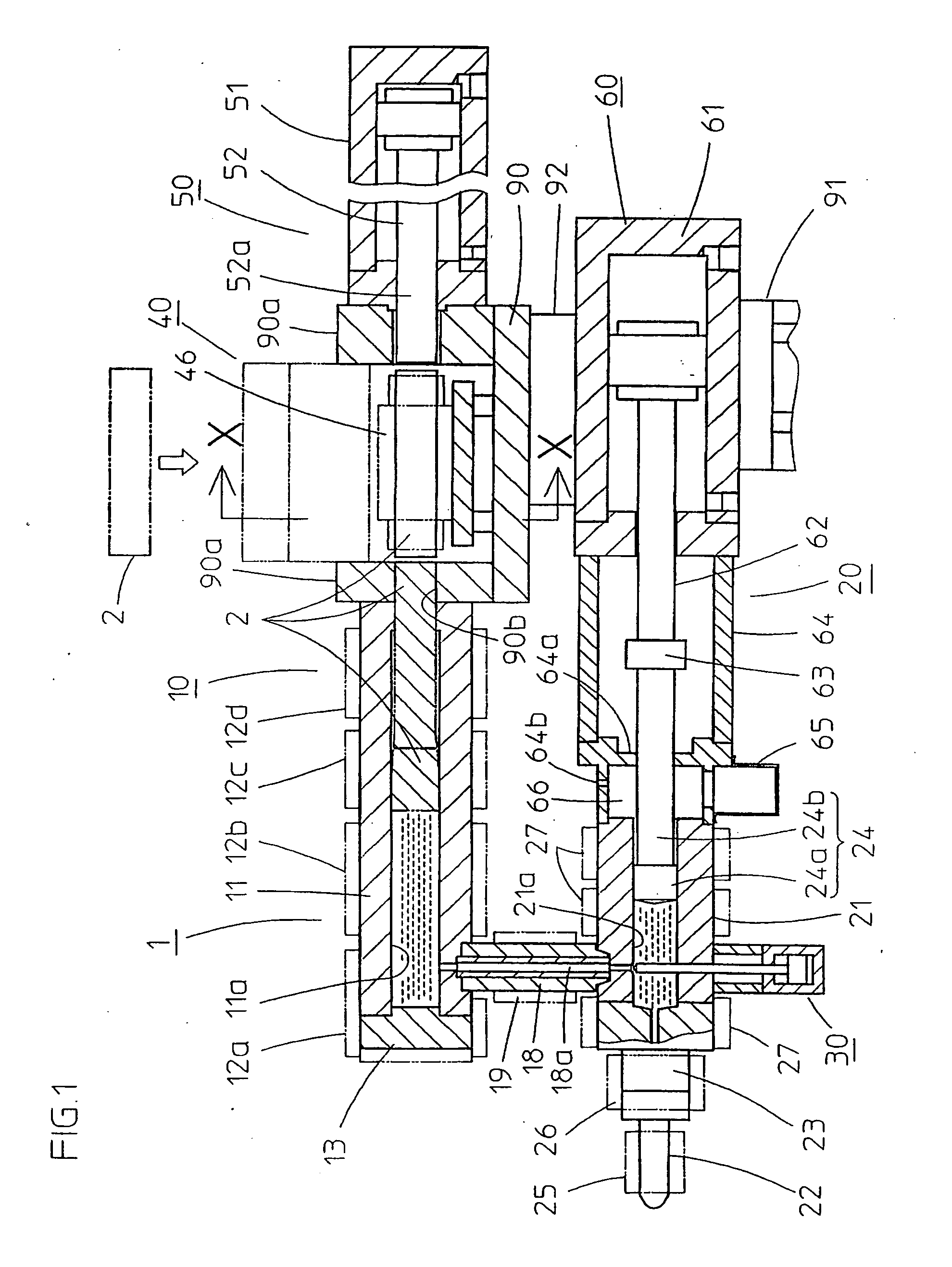
[0073] On the other hand, with the melting device of a second embodiment, the melting cylinder has the structure as shown in FIG. 6 and FIG. 7. FIG. 6 is a cross sectional drawing showing the schematic structure of this melting device, and FIG. 7 is a cross sectional drawing showing main parts of the melting device. Structural elements in the drawing that have already been described have the same reference numerals, and description thereof is omitted.

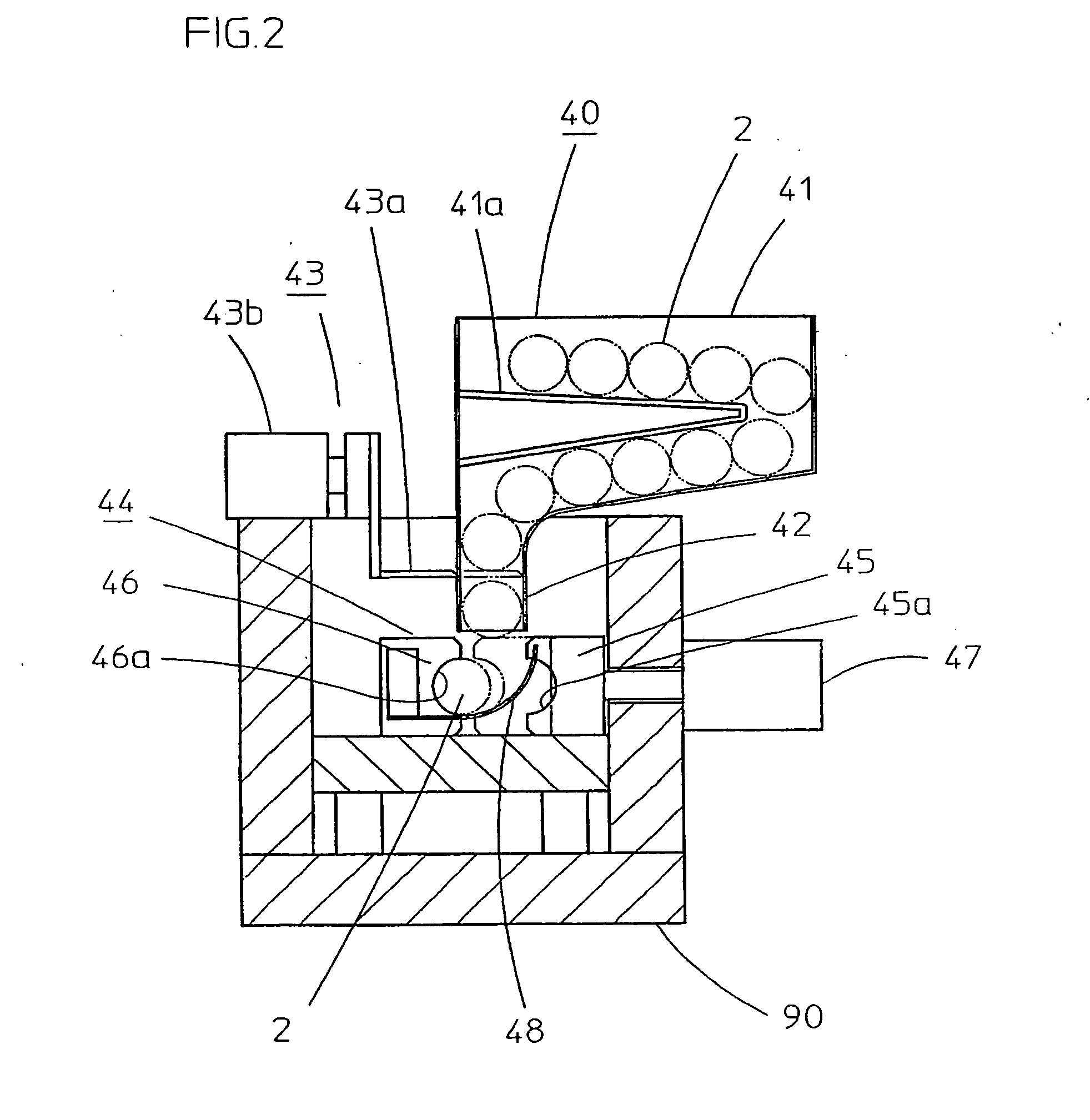
[0074] In addition to the central frame member 90, billet supply device 40 and billet inserting device 50 already described, this melting device 10 comprises a melting cylinder 111 fixed to the side plate 90a of the central frame member 90, and a cooling sleeve 112 fitted between this cylinder 111 and the side plate 90a. The central frame member 90 is the same as the central frame member already described, and also has through holes 90b in two opposed side plates 90a, but in particular a cooling duct 90d in which cooling fluid is suppli...


PUM

PropertyMeasurementUnit
Temperatureaaaaaaaaaa
Diameteraaaaaaaaaa
Volumeaaaaaaaaaa

Abstract

An injection device for a light metal injection molding machine includes a melting device for melting light metal material into molten metal, plunger injection device for carrying out injection of molten metal using a plunger after the molten metal is metered into an injection cylinder from the melting device, connecting member including a connecting passage for connecting the melting device and the plunger injection device, and backflow prevention device for preventing backflow of molten metal by opening and closing the connecting passage.

Description

FIELD OF THE INVENTION [0001] The present invention relates to an injection device for a light metal injection molding machine for melting a light metal material such as magnesium, aluminum or zinc and injecting this molten metal into a mold to perform molding, and, in particular, relates to an injection device for a light metal injection molding machine for melting a light metal material inside a melting cylinder of a melting device, supplying and metering the molten metal to an injection cylinder of a plunger injection device provided beside the melting device, and injecting a measured amount of molten metal using a plunger to perform molding. BACKGROUND OF THE INVENTION [0002] Conventionally, molding of light metal alloys has been carried out using a die casting method exemplified by a hot chamber method and a cold chamber method. In particular, magnesium alloy molding is also carried out using thixotropic molding as well as the above-described die casting methods. [0003] Die cas...

Claims


Application Information

Patent Timeline
IPC IPC(8): B22D17/10B22D17/20B22D17/28B22D17/30
CPCB22D17/10B22D17/30B22D17/28B22D17/2015
Inventor FUJIKAWA, MISAO
Owner SODICK CO LTD
Why Eureka
Try Eureka