Piezoelectric resonator, filter, and duplexer

a resonator and piezoelectric technology, applied in piezoelectric/electrostrictive/magnetostrictive devices, piezoelectric/electrostrictive/magnetostriction machines, piezoelectric/electrostrictive/magnetostriction machines, etc., can solve the problem of partially losing the energy essentially used for excitation of vibration in the piezoelectric body, easy to excite unwanted components, etc. problem, to achiev

Active Publication Date: 2005-03-17
PANASONIC CORP
View PDF3 Cites 141 Cited by
  • Summary
  • Abstract
  • Description
  • Claims
  • Application Information

AI Technical Summary

Benefits of technology

[0013] Therefore, an object of the present invention is to provide a piezoelectric resonator capable of preventing unwanted vibration due to vibration leakage, thereby suppressing occurrence of spurious components, a filter using the same piezoelectric resonator, and a duplexer using the same piezoelectric resonator.

Problems solved by technology

However, if the electrode size is increased, a contact area between the electrode and the substrate is inevitably increased in order to ensure strength, so that spurious components are readily excited.
Accordingly, if the electrode size is increased, the piezoelectric resonator is susceptible to, for example, vibration in the portion A, as well as to a fundamental mode (a ½ wavelength mode, the frequency f1) of desired vibration in the thickness direction, and therefore unwanted vibration readily occurs in the vicinity of a main resonance frequency (f1).
This means that energy essentially used for excitation of vibration in the piezoelectric body is partially lost due to vibration leakage.
Such pass characteristics lead to degradation of communication quality.

Method used


Image

  • Piezoelectric resonator, filter, and duplexer
  • Piezoelectric resonator, filter, and duplexer
  • Piezoelectric resonator, filter, and duplexer

Examples


first embodiment

[0033] (First Embodiment)

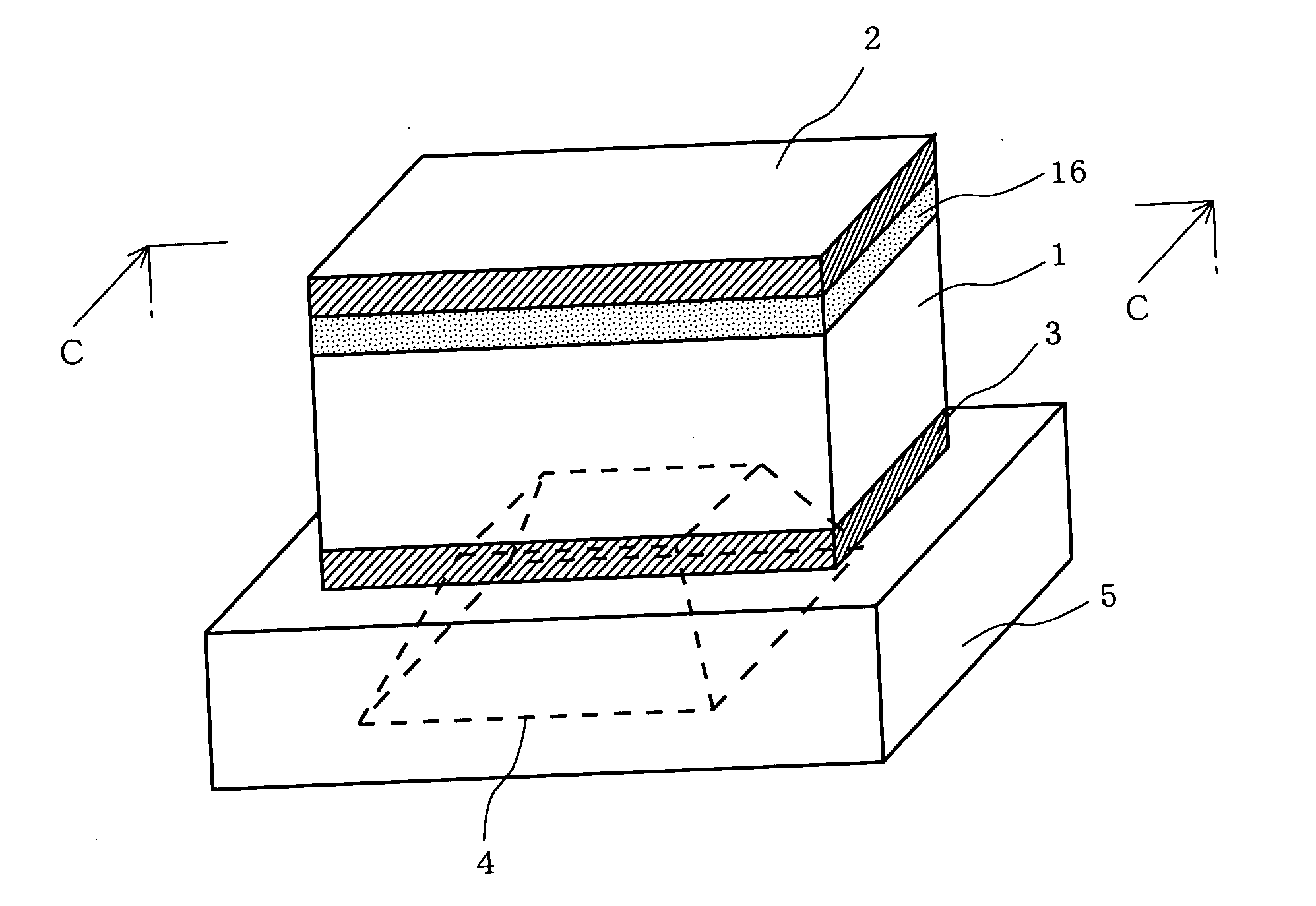
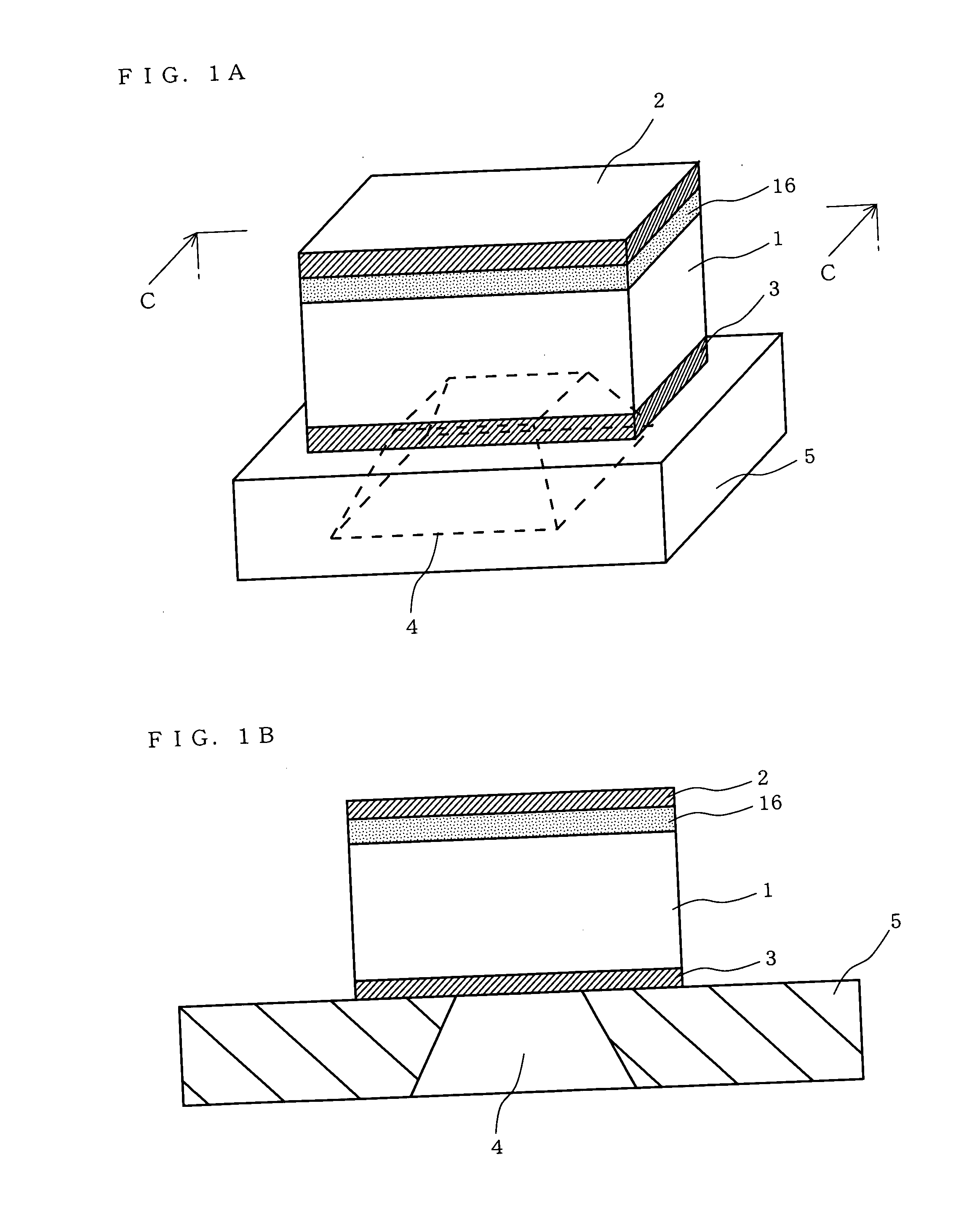
[0034]FIG. 1A is a perspective view showing an exemplary structure pattern of a piezoelectric resonator according to a first embodiment of the present invention. FIG. 1B is a cross-sectional view taken along line C-C shown in FIG. 1A. In FIGS. 1A and 1B, the piezoelectric resonator according to the first embodiment is structured such that on a substrate 5 having a cavity 4 provided therein, a lower electrode 3, a piezoelectric body 1, a spurious component control layer 16, and an upper electrode 2 are formed in this order from bottom up. The upper electrode 2 and the lower electrode 3 are composed of, for example, molybdenum (Mo) . The piezoelectric body 1 is composed of, for example, a piezoelectric material such as aluminum nitride (AlN). The spurious component control layer 16 is composed of a metallic material, a dielectric material, or a piezoelectric material (which is different from the material of the piezoelectric body 1 included in the piezoelectri...

second embodiment

[0052] (Second Embodiment)

[0053] A second embodiment is described with respect to another structure pattern of the piezoelectric resonator described in the first embodiment. Note that the structure pattern described in the second embodiment is merely an example, and various other structure patterns are conceivable.

[0054] (1) In one exemplary structure, a spurious component control layer 6 is provided between the lower electrode 3 and the substrate 5, and the spurious component control layer 16 is provided between the upper electrode 2 and the piezoelectric body 1 (FIG. 4A). With this structure, it is possible to increase adhesive strength between the piezoelectric resonator and the substrate 5, while maintaining an effect of preventing any spurious component from occurring between the resonance frequency fr and the antiresonance frequency fa, whereby it is possible to increase the reliability of the piezoelectric resonator. Note that the spurious component control layer 6 and the s...

third embodiment

[0063] (Third Embodiment)

[0064]FIG. 5A is a cross-sectional view showing an exemplary structure pattern of a piezoelectric resonator according to a third embodiment of the present invention. In FIG. 5A, the piezoelectric resonator according to the third embodiment is structured such that on the substrate 5 having the cavity 4 provided therein, the lower electrode 3, the spurious component control layer 16, the piezoelectric body 1, the upper electrode 2, an additional piezoelectric body 51, and an additional electrode 52 are formed in this order from bottom up. The upper electrode 2, the lower electrode 3, and the additional electrode 52 are composed of, for example, molybdenum (Mo). The piezoelectric body 1 and the additional piezoelectric body 51 are composed of, for example, a piezoelectric material such as aluminum nitride (AlN). The spurious component control layer 16 is composed of a metallic material, a dielectric material, or a piezoelectric material (which is different from...


PUM


Abstract

A piezoelectric resonator of the present invention is structured such that on a substrate 5 having a cavity 4 formed therein, a lower electrode 3, a piezoelectric body 1, a spurious component control layer 16, and an upper electrode 2 are formed in this order from bottom up. The spurious component control layer 16 is a layer for controlling a spurious frequency, and composed of, for example, a metallic material, a dielectric material, or a piezo electric material. By additionally providing the spurious component control layer 16, it is made possible to cause variation of the spurious frequency due to unwanted variation to become greater than variation in resonance frequency of the main resonance of the piezoelectric resonator. Thus, it is possible to realize a piezoelectric resonator having an admittance frequency response where no spurious component occurs between resonance frequency fr and antiresonance frequency fa.

Description

BACKGROUND OF THE INVENTION [0001] 1. Field of the Invention [0002] The present invention relates to a piezoelectric resonator, and more particularly to a piezoelectric resonator capable of suppressing occurrence of spurious components, a filter using the same piezoelectric resonator, and a duplexer using the same piezoelectric resonator. [0003] 2. Description of the Background Art [0004] Elements included in an electronic apparatus such as a portable apparatus are required to be reduced in size and weight. For example, a filter for use in a portable apparatus is required to be precisely adjustable for a frequency response as well as to be reduced in size. As an exemplary filter which satisfies the above requirements, a filter using a piezoelectric resonator is known (for example, see Japanese Laid-Open Patent Publication No. 60-68711). [0005] Hereinafter, referring to FIGS. 10A-10D, a conventional piezoelectric resonator will be described. FIG. 10A is a cross-sectional view showing...

Claims


Application Information

Patent Timeline
Patent Type & Authority Applications(United States)
IPC IPC(8): H03H9/02H03H9/17H03H9/58
CPCH03H9/02094H03H9/02102H03H9/0211H03H9/173H03H9/589H03H9/175H03H9/585H03H9/588H03H9/174
Inventor NAKATSUKA, HIROSHIONISHI, KEIJINAKAMURA, HIROYUKIYAMAKAWA, TAKEHIKO
Owner PANASONIC CORP
Why Eureka
Try Eureka