Network scanning system

Inactive Publication Date: 2005-03-17
CANON DENSHI KK
View PDF10 Cites 28 Cited by
  • Summary
  • Abstract
  • Description
  • Claims
  • Application Information

AI Technical Summary

Benefits of technology

[0009] The present invention has been made to solve the above problems, and provides a technique for enabling use of image scanner device, which is connected to a general information process

Problems solved by technology

As it is desirable that the image scanner device can also be shared on the network, several network-connectable scanner devices (generally many of them have a complex machine form) are known, however, such devices are very expensive.
According to the technique disclosed in the above patent document, the existing image scanner device can be connected to the network via the scan box, however, as the scan box is contr

Method used


Image

  • Network scanning system
  • Network scanning system
  • Network scanning system

Examples


Example

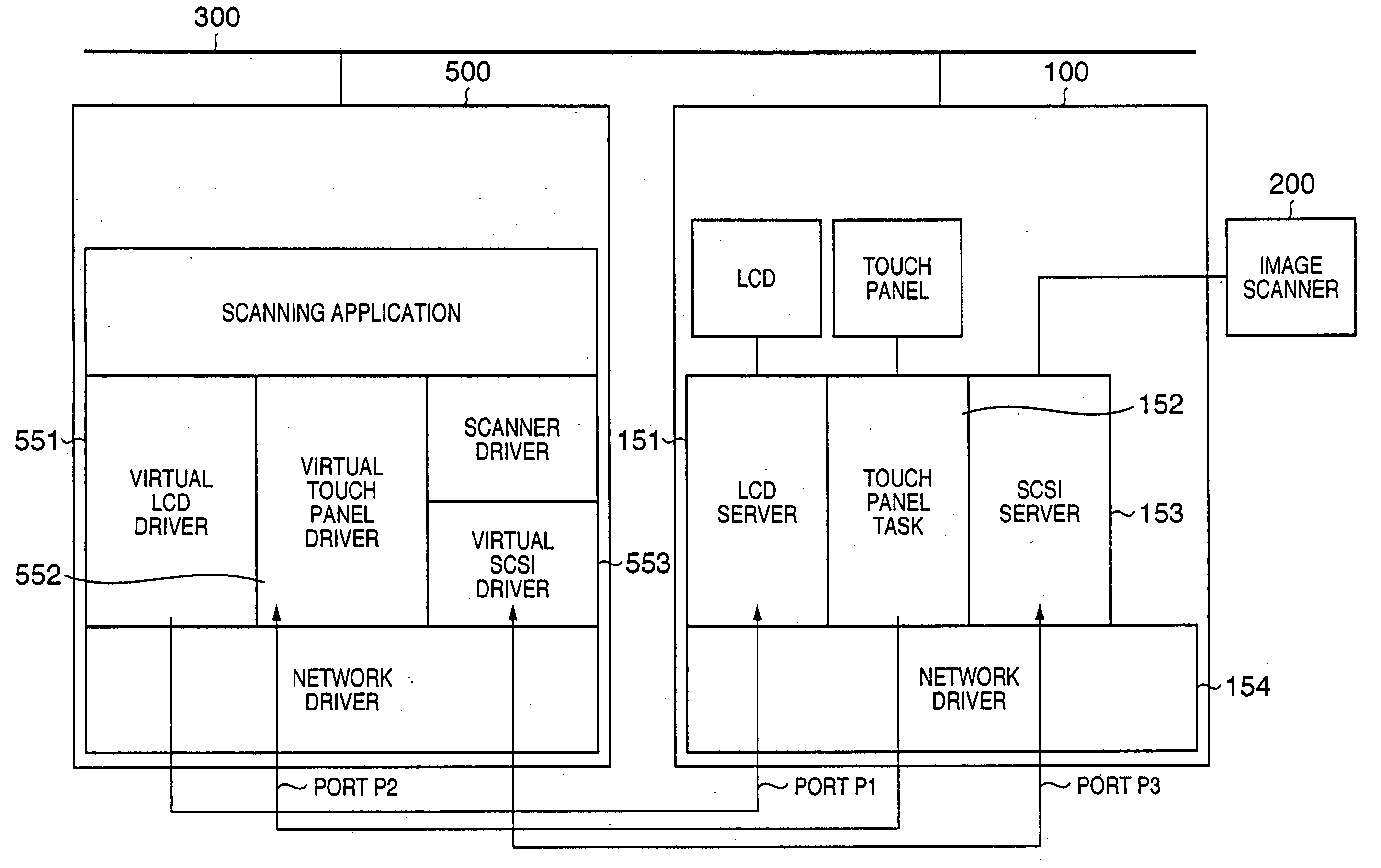
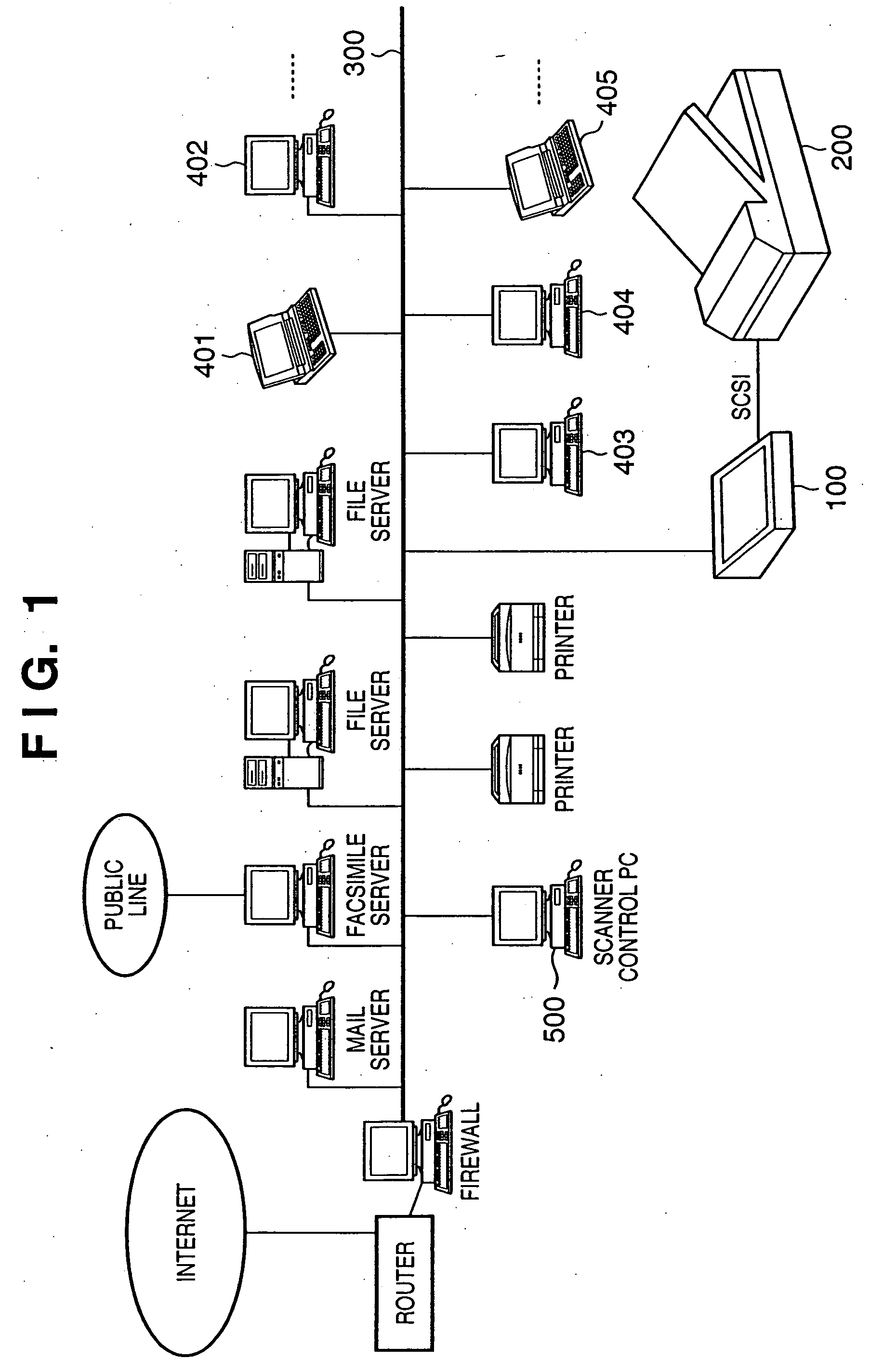
[0033]FIG. 1 illustrates the form of a system utilizing a scanner / network connection apparatus according to a first embodiment of the present invention.

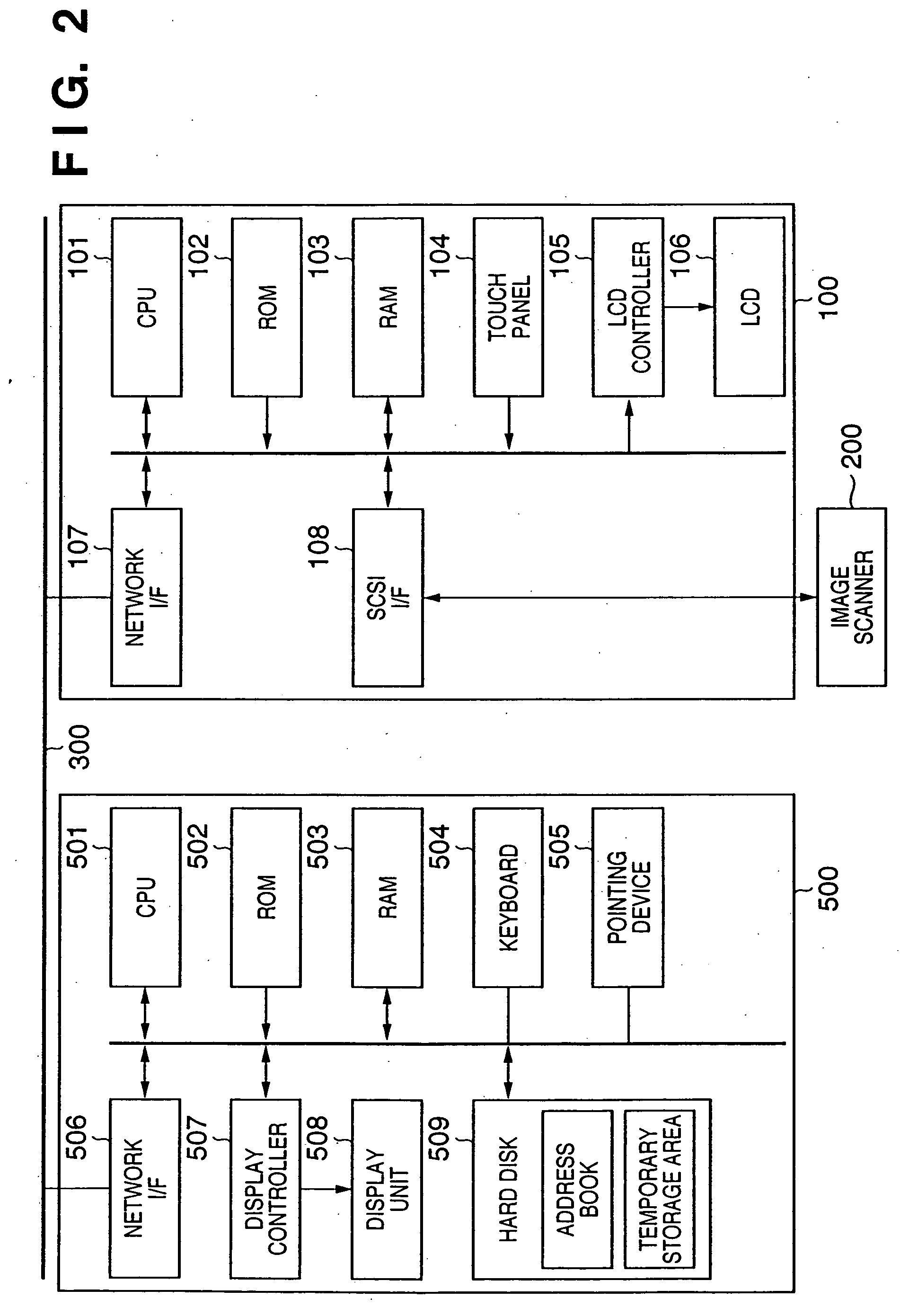
[0034] In FIG. 1, reference numeral 100 denotes a scanner / network connection apparatus having a network interface and a SCSI interface; 200, an image scanner device (hereinbelow, simply referred to as a “scanner” having a SCSI interface; 300, a local area network (hereinbelow, simply referred to as a “network”) such as an Ethernet; 401 to 405, personal computers (PCs) connected to the network 300 used by respective users; and 500, a control PC which manages and remote-controls the scanner / network connection apparatus 100. Note that there is no hardware difference between the control PC 500 and the PCs 401 to 405, but the difference is whether or not an application to control the scanner / network connection apparatus and various driver programs to be described later operate. Further, as it will be apparent from a description to be mad...

Example

Second Embodiment

[0161] In the above embodiment, when an original image is read by the scanner 200 and the scanner / network connection apparatus 100 transmits the image data to the scanner control PC 500, the CPU 501 of the scanner control PC 500 expends much CPU power in image data reception and storage processing.

[0162] This means that during original image reading, it is difficult to update a display image on the scanner / network connection apparatus 100 from the scanner control PC 500, and if the update is performed, the speed of image data transmission may be lowered. Accordingly, to place a high priority on the image data transmission speed, the display image on the LCD 106 of the scanner / network connection apparatus 100 cannot be changed. However, to the user of the scanner / network connection apparatus 100, during transmission of original image data, the screen image of the LCD 106 is frozen, and the user may feel anxious about the processing.

[0163] Accordingly, in the secon...


PUM


Abstract

An image scanner device connected to a general information processing apparatus can be used on a network at a low cost, and further, the firmware of hardware for this purpose can be a maintenance-free firmware, thus user's convenience can be improved. A scanner/network connection apparatus 100 to connect a scanner 200 to a network 300 has an LCD server to drive a LCD as a display unit, a touch panel task to transmit a touch position on a touch panel, and a SCSI server to connect the scanner 200 to the network. A PC 500 to control the scanner has a virtual LCD driver, a virtual touch panel driver, and a virtual SCSI driver, operating to provide an environment as if the LCD, the touch panel and the image scanner of the scanner/network connection apparatus 100 are connected to the PC 500. The virtual LCD driver draws a screen image as a user interface for various operations, and the result of drawing is displayed on the LCD of the scanner/network connection apparatus 100. Thus an interactive operation environment can be provided to the user.

Description

FIELD OF THE INVENTION [0001] The present invention relates to a technique of connecting an image scanner device to a network. BACKGROUND OF THE INVENTION [0002] Generally, an image scanner device is connected to a general information processing apparatus such as a personal computer or a work station (hereinbelow, generally referred to as a “PC”) via a SCSI (Small Computer System Interface) or a USB (Universal Serial Bus) interface. [0003] As applications of the image scanner device, optical character recognition (OCR), filing and other various applications are known. In recent years, the variety of uses for the image scanner device such as generation of attachment to an electronic mail is further increased. [0004] On the other hand, in workplaces, employees respectively use one PC, and the PCs are connected to a network to share network resources (files, printers etc.). As it is desirable that the image scanner device can also be shared on the network, several network-connectable s...

Claims


Application Information

Patent Timeline
IPC IPC(8): H04N1/00
CPCH04N1/00222H04N1/00225H04N1/00344H04N1/00384H04N1/0083H04N1/00811H04N2201/0036H04N2201/0039H04N2201/0081H04N1/00411
Inventor FUJITA, DAISUKEHIGUCHI, HIROKAZUOKAWARA, MINORUMASAO, NOZOMIKOMURO, HIROSHI
Owner CANON DENSHI KK
Why Eureka
Try Eureka