

Autostereoscopic optical apparatus
a display apparatus and autostereoscopic technology, applied in optics, electrical devices, instruments, etc., can solve the problems of time-based multiplexing, introducing the inherent problem of image flicker, and not compensating for these inherent drawbacks, so as to improve viewing pupil size, reduce lagrange invariant constraints on available luminance, and increase imaging display
- Summary
- Abstract
- Description
- Claims
- Application Information
AI Technical Summary
Benefits of technology
Problems solved by technology
Method used
Image

Examples
first embodiment
[0068] First Embodiment of Image Generation System
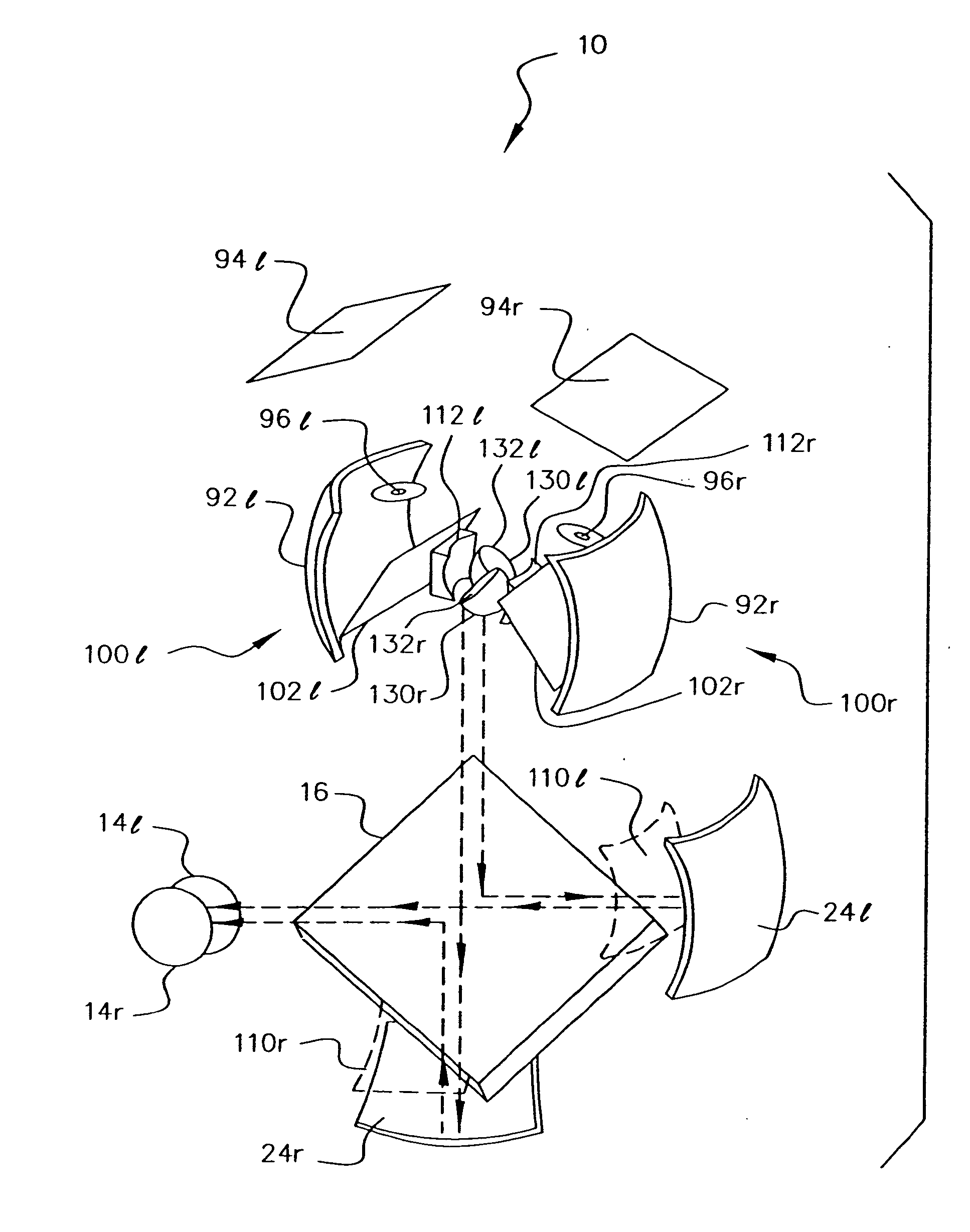
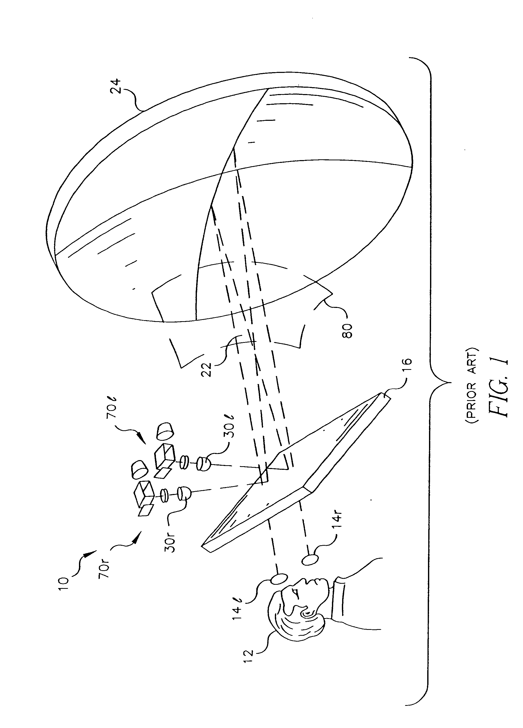
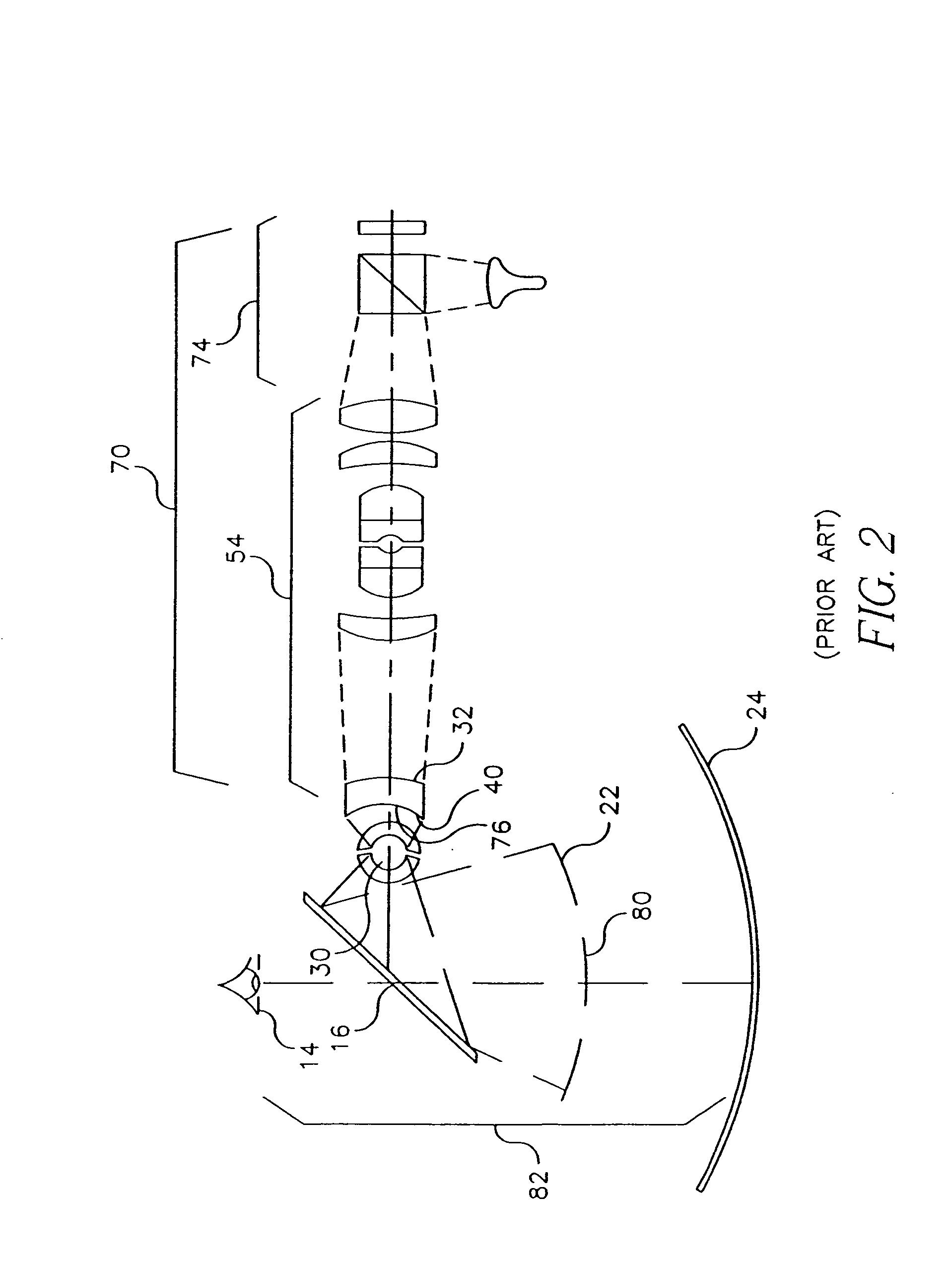
[0069] Referring to FIG. 5, there is shown a first embodiment of an image generation system 100 for forming a curved image 110 for projection according to the present invention, as disclosed in the commonly-assigned copending U.S. patent application Ser. No. 10 / 393,236. Curved image 110 serves the function of intermediate curved image 80 shown in FIGS. 1 and 2. As described with reference to FIG. 3, image source 94 provides image-bearing light to curved mirror 92 through aperture stop location 96. Referring now to FIG. 5, a beamsplitter 102 is used to direct an intermediate image 90′ so that it is concentric to ball lens assembly 30, which could alternately be embodied as hemispheric lens assembly 60, as was shown in FIG. 4b. Because the light is being directed by curved mirror 92 toward its center of curvature Cs, rather than towards the center of curvature Cball of ball lens assembly 30, some portion of the light does not enter the...
second embodiment
[0071] Second Embodiment of Image Generation System
[0072] Referring to FIG. 6, there is shown an improved embodiment of image generation system 100 in which a field lens 112 is positioned along the output axis where intermediate image 90 is formed. By positioning field lens 112 at this location, intermediate image 90 is not substantially changed; however, light from intermediate image 90 is directed toward center of curvature Cball of ball lens assembly 30. Once again, it is significant to observe that ball lens assembly 30 shares the same center of curvature Cball as intermediate image 90, but that this is not identical to the center of curvature Cs of curved mirror 92 or to the imaged center of curvature Cs', towards which light from curved mirror 92 is directed. The function of field lens 112 is, then, to image Cs onto Cball without substantially affecting the image quality of intermediate image 90. By doing this, field lens 112 essentially redirects light in order to fill pupil ...
PUM
 Abstract
Description
Claims
Application Information